39/221
Siemens Switzerland Ltd User manual RVS61.843 CE1U2355en_02
HVAC Products 5 Handling 23. November 2007
Other displays:
− Room temp
− Solar flow temp
− Room temp min
− Solar return temp
− Room temp max
− 24-hour yield solar energy
− Room setpoint 1 − Total yield solar energy
− Room setpoint 2 − Swimming pool temp
− Room setpoint P − Swimming pool setpoint
− Outside temp
− Outside temp min
− Outside temp max
− State heating circuit 1
− DHW temp 1
− State heating circuit 2
− DHW temp 2 − State heating circuit P
− Buffer temp 1
− State cooling circuit
− Buffer temp 2
− State DHW
− Buffer setpoint − State heat pump
− Flow temp 1 − State solar
− Flow temp setpoint 1
− State buffer
− Flow temp 2
− State swimming pool
− Flow temp setpoint 2 − Error message
− Flow temp setpoint P
− Maintenance message
− Collector temp 1
− Floor curing function
− Setpoint HP − Date and time of day
− Flow temp HP
− Telephone customer service
− Return temp HP
− Source inlet temp
− Source outlet temp
− Remain stage 1 off time min
− Remain stage 2 off time min
− Remain stage 1 on time min
− Remain stage 2 on time min
In exceptional cases, the basic display shows one of the following symbols:
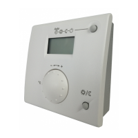
Error messages
If this symbol appears, an error in the
plant has occurred. Press the info button
and read further information.
Text3 Text4
0
4 8 12 16 20 24
AUTO
2359Z140
30:Flow sensor 1
Error
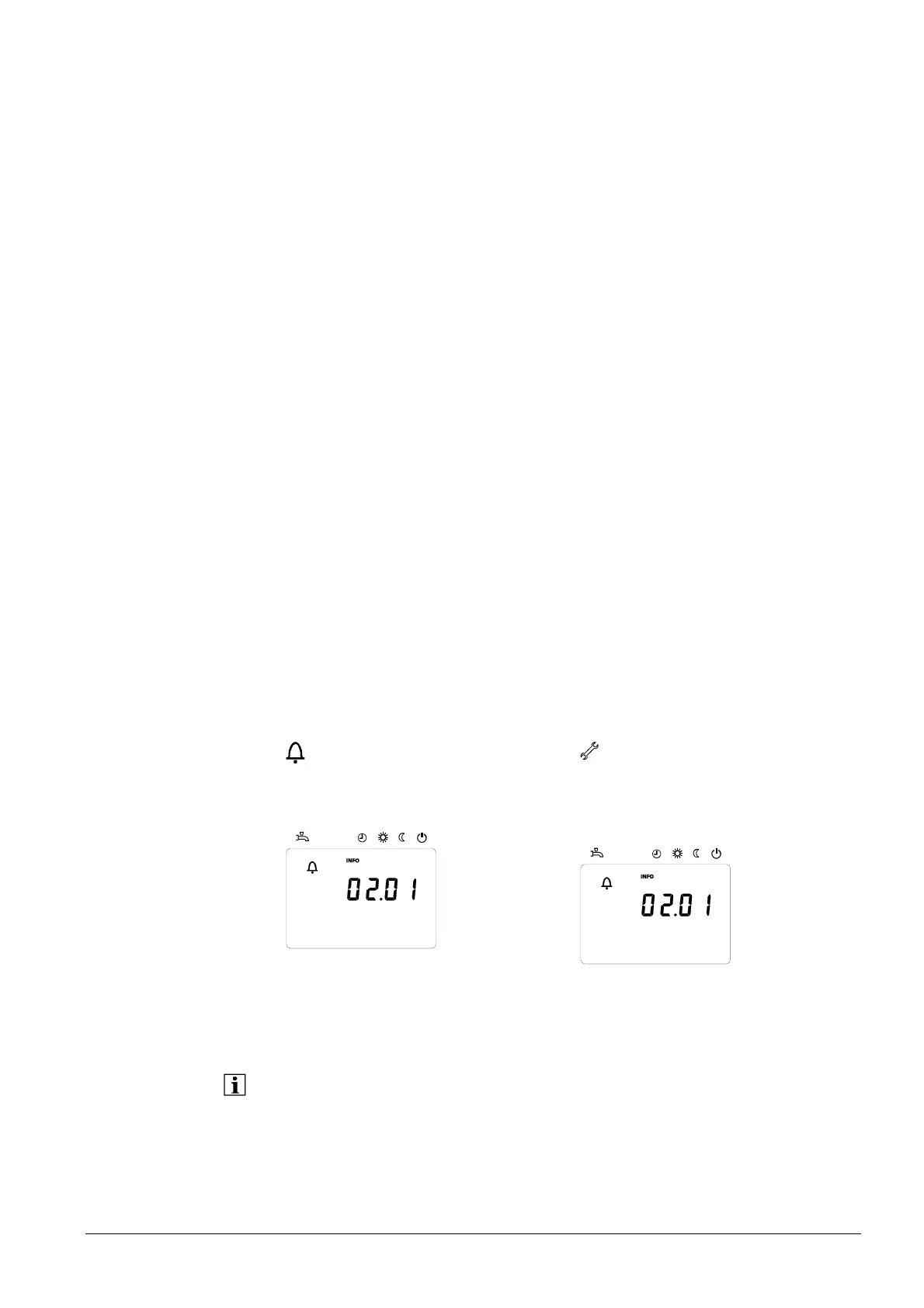
Service or special operation
If this symbol appears, a maintenance
message is delivered or the plant has
changed to special operation. Press the
info button and read further information.
Text3 Text4
0
4 8 12 16 20 24
AUTO
2359Z140
30:Flow sensor 1
Error
The LPB number on the display indicates the device in the LPB system from which the
error or maintenance message, or special operation, was triggered. The first 2 digits
give the segment address, the 2 digits after the dot the device address.
Hence, 02.01 denotes segment 2, device 1.
An error list is given in section “Errors“, starting on page 168.
Exception
 Loading...