Q-Series Outdoor Air and Critical Environment Technical Instructions
Relative Humidity and Relative Humidity & Temperature Sensors Document Number 155-755
February 28, 2013
Siemens Industry, Inc. Page 3
Ordering
Information
The AQF3100 outdoor mounting kit listed under Accessories must be ordered as a
separate item.
The circular connector with its screwed plug is delivered uninstalled (QFA4160).
Equipment
Combinations
The Q-Series Relative Humidity and Relative Humidity & Temperature Sensors can be
used with all types of systems and devices that can acquire and handle the sensor’s 0
to 10 Vdc or 4 to 20 mA output signal.
Technical Design
Relative Humidity
The sensor acquires relative humidity via its capacitive sensing element; the
capacitance varies as a function of the relative humidity of the ambient air. An electronic
circuit converts the sensor's signal to a continuous 0 to 10 Vdc or 4 to 20 mA signal,
which corresponds to a relative humidity of 0 to 100%.
Temperature
The sensor acquires the temperature via its sensing element; the electrical resistance
varies according to the temperature of the ambient air.
This variation is converted to an active 0 to 10 Vdc or 4 to 20 mA output signal,
corresponding to a temperature range of 32°F to 122°F, -31°F to 95°F, or -40°F to
158°F (0°C to 50°C, -35°C to 35°C, or -40°C to 70°C). The measuring range is selected
by repositioning factory-supplied jumpers.
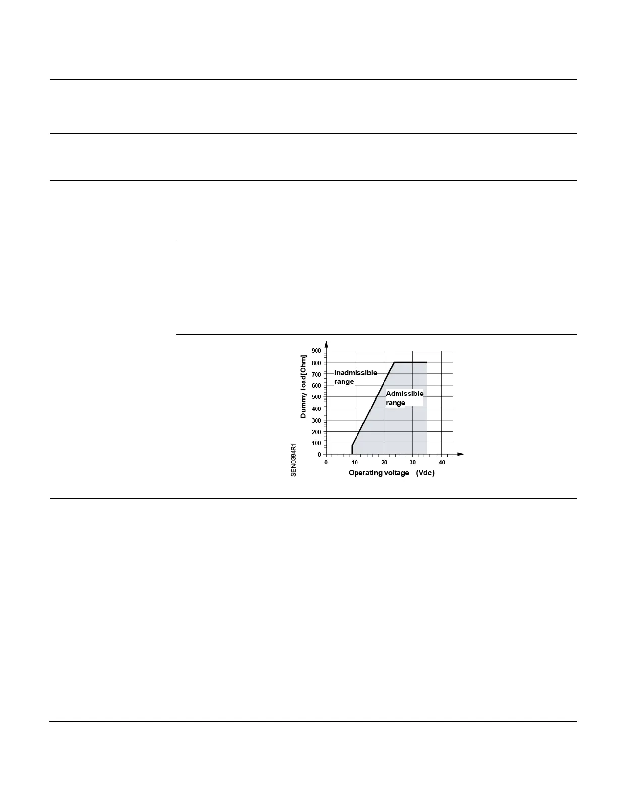
Resistive Load Diagram
Figure 1. Output Signal, Terminal I1/I2.
Mechanical Design
The room sensor consists of housing, printed circuit board, connection terminals and
measuring rod. The housing consists of two parts: base and removable cover
(screwed). The QFA4160 also has a circular connector.
The measuring circuit and the setting element are located inside the cover of the printed
circuit board; the connection terminals are in the base. The housing and measuring rod
are screwed together.
The sensing elements are located at the end of the measuring rod and are protected by
a screw-on filter cap.
For the QFA31 Series, the M16 cable entry gland supplied with the sensor can be
screwed into the bottom of the base. If the sensor is used outdoors, that opening must
be closed off and the prepared hole on the opposite side of the base knocked out.
For the QFA41 Series, the cable entry is made via the circular connector, which
consists of a coupling piece with M16 thread and a connector with a screwed plug. The
coupling piece is secured to the housing and internally wired. The sensor is designed
for wall mounting.
 Loading...