25 / 40
Siemens RDF300…/RDF340.../RDF400… Basic Documentation CE1P3076en
Building Technologies 4BFunctions 28 Aug 2008
In the event of a power failure, the clock stops, but its last time is stored. This time
information is reloaded and starts running after power up. The clock flashes to
indicate that there was a power failure until the time is confirmed by pressing
, or
readjusted by following the above procedure.
4.11 Error handling
When the room temperature is outside the measuring range, i.e. above 49 °C or
below 0 °C, the limiting temperatures flash, e.g. “0 °C” or “49 °C”.
Output Y11 is energized if the current setpoint is not set to “OFF”, the controller is
in heating mode and the temperature is below 0 °C. For all other cases, output Y11
is de-energized. The controller resumes Comfort mode after the temperature
returns to within the measuring range.
4.12 Infrared remote control
Use the IRA210 infrared remote control to operate a controller with built-in infrared
receiver. The following operations can be carried out remotely:
• Select operating modes Standby, Comfort mode or Auto Timer.
• Adjust setpoint in Comfort mode.
• Select fan modes Automatic or Manual.
A buzzer in the thermostat indicates remote control command reception.
Infrared remote control can be disabled via parameter P70.
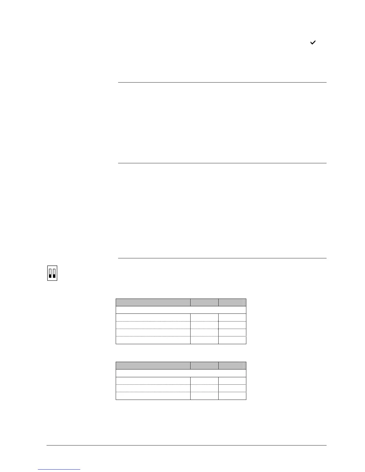
4.13 DIP switches
Use the DIP switches on the inner side of the front panel to commission the basic
controller applications prior to snapping it to the base.
RDF300…/RDF400… have the following DIP switch settings:
DIP switch number
1 2
Application
2-pipe OFF OFF
2-pipe, 3 position ON OFF
2-pipe & electrical heater OFF ON
4-pipe
1)
ON ON
RDF340 has the following DIP switch settings:
DIP switch number
1 2
Application
2-pipe OFF OFF
2-pipe & electrical heater OFF ON
4-pipe
1)
ON ON
1) Factory setting
Note: During startup, the controller reloads the control parameter factory settings
after each DIP switch settings change.
Power failure
Temperature out of
range
ON
1 2
RDF300…/RDF400…
RDF340
 Loading...