29 / 40
Siemens RDF300…/RDF340.../RDF400… Basic Documentation CE1P3076en
Building Technologies 5BHandling 28 Aug 2008
5 Handling
5.1 Mounting and installation
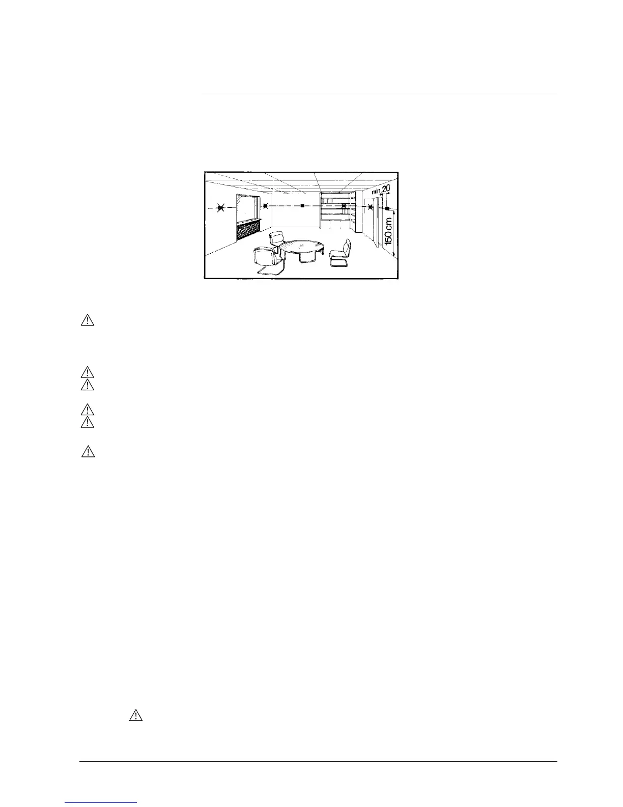
Mount the room controller on a recessed rectangular conduit box with 60.3mm
fixing centers. Do not mount on a wall in niches or bookshelves, behind curtains,
above or near heat sources, or exposed to direct solar radiation. Mount about
1.5 m above the floor.
• Devices must be mounted on clean, dry indoor place and not be exposed to
dripping or splashing
See the mounting instructions G3076 enclosed with the controller.
• Comply with local regulations to wire, fuse and earth the controller
• Properly size the cables to the controller, fan and valve actuators for AC 230 V
mains voltage
• Use only valve actuators rated for AC 230 V on RDF300…/RDF400…
• The AC 230 V mains supply line must have an external fuse or circuit breaker
with a rated current of no more than 10 A
• Isolate the cables of SELV inputs X1-M/X2-M if the conduit box carries AC 230 V
mains voltage
• Inputs X1-M or X2-M of different units (e.g. summer/winter switch) may be
connected in parallel with an external switch. Consider overall maximum contact
sensing current for switch rating
• No metal conduits
• No cables provided with a metal sheath
• Disconnect from supply before opening the cover
Set the controller application via the DIP switches before snapping the front panel
on the mounting base.
After power is applied, the controller carries out a reset during which all LCD
segments flash indicating that the reset was correct. After the reset, which takes
about 3 seconds, the controller is ready for commissioning by qualified HVAC staff.
The control parameters of the controller can be set to ensure optimum performance
of the entire system (see “Set control parameters”).
• The control sequence may need to be set via parameter P01 depending on the
application. The factory setting for the 2-pipe application is “Cooling only”; and
“Heating and Cooling” for the 4-pipe application
• When the controller is used with a compressor, the minimum output on-time
(parameter P48) and off-time (parameter P49) for Y11/Y21 must be adjusted to
avoid damaging the compressor and shortening its life
Mounting
Wiring
Commissioning
Control sequence
Compressor-based
application
 Loading...