34 / 40
Siemens RDF300…/RDF340.../RDF400… Basic Documentation CE1P3076en
Building Technologies 7BMechanical design 28 Aug 2008
7 Mechanical design
The controller consists of 2 parts:
• Front panel accommodating the electronics, operating elements and built-in room
temperature sensor.
• Mounting base with the power electronics.
The rear of the mounting base contains the screw terminals. The base fits on a
rectangular conduit box with 60.3 mm fixing centers. Slide the front panel in the
mounting base and snap on.
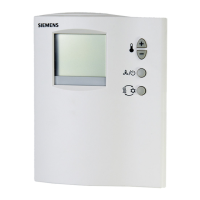
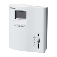
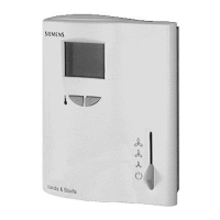
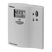
1. Operating mode selector/Standby
2. Change fan operation
3. Adjust setpoint and control parameters
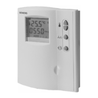
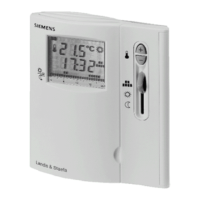
1. Change operating mode selector
2. Change fan operation
3. Adjust setpoint, control parameters and time
of day
4. Auto Timer program
5. Standby
6. Set time of day and weekday
7. Confirm
8. Infrared receiver
1. Operating mode
Standby mode
AUTO
Auto Timer mode*
Comfort mode
Energy Saving mode
* only on RDF400…
2. Display room temperature, setpoints and
control parameters.
Symbol used to display the current
room temperature
3. Heating/cooling mode
Cooling mode
Heating mode,
Electrical heater active
4. Fan mode
Auto fan active
Fan speed low, medium, high
5. Additional user information (RDF3xx) or
current time of day (RDF400)
6. Weekday 1..7 (1 = Monday/7 = Sunday)*
7. Keypad lock active
8. Condensation in room (dewpoint sensor
active)
9. Indicate alarm or reminder
Operation and settings
RDF300…/RDF340…
RDF400…
Display
2
1
3
2
1
5
8
6
3
4
7
1
2
3
4
5
6
9
7
8
 Loading...