'
OPERATION
•
-
-~----------------~--,---
SUPPLY
L[:::r1----------....--
: :
I
:csc
~1
r'1
1sr
5
BB-1
88-2
I
.I:
x'~T
A
(c\
r,i
,
BB
s 4 I
._
I
A ' ~--1,. '
•
4A
y
••
y '
,c
4
0
'
•
'(
I
3
•
~Mo
:
rl:.l-~-------
-
-----
:
-
-•--------------------,1.--
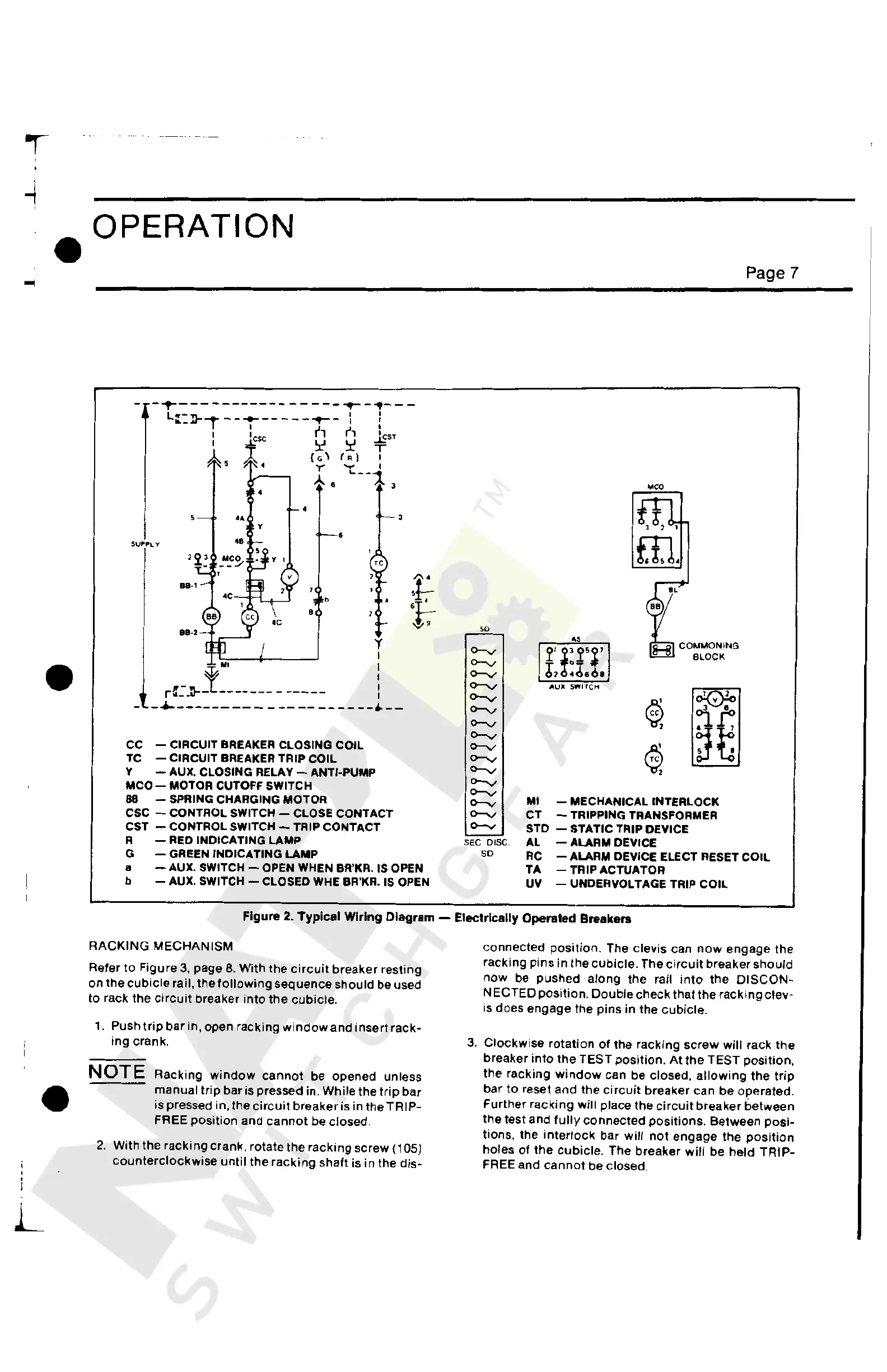
CC - CIRCUIT BREAKER CLOSING COIL
TC - CIRCUIT
BREAKER TRIP COIL
Y
-AUX.
CLOSING
RELAY-ANTI-PUMP
MCO-
MOTOR CUTOFF SWITCH
88 - SPRING CHARGING MOTOR
CSC - CONTROL SWITCH - CLOSE CONTACT
CST - CONTROL SWITCH - TRIP CONTACT
R -
REO
INDICATING LAMP
G - GREEN INDICATING LAMP
a - AUX. SWITCH - OPEN WHEN BR'KR. IS OPEN
b - AUX.
SWITCH - CLOSED WHE BR'KR.
IS
OPEN
SD
<>-v
<>-v
<>-v
<>-v
<>-v
<>-v
<>-v
<>-v
0-V
0-V
<>-v
0-V
<>-v
<>-v
<>-v
0-V
SEC DISC
SD
.,
COMMON
ING
i'
i:j'i'
BLOCK
6,
,6, ,
AUil
SWITCl-i
o:@o
~
1r.
~t
<m
Ml
- MECHANICAL INTERLOCK
CT
- TRIPPING TRANSFORMER
STD - STATIC TRIP DEVICE
AL - ALARM DEVICE
Page 7
RC
- ALARM DEVICE ELECT RESET
COIL
TA
- TRIP ACTUATOR
UV
- UNDERVOLTAGE TRIP
COIL
Figure
2.
Typical Wiring Diagram - Electrically Operated Breakers
•
L
RACKING
MECHANISM
Refer
to
Figure
3,
page
8.
With
the
circuit
breaker
resting
on
the
cubicle
rail, the
following
sequence
should
be used
to
rack the
circuit
breaker
into
the
cubicle.
1.
Push
trip
bar
in,
open
racking
window
and
insert
rack-
ing
crank.
NOTE
Racking
window
cannot
be
opened
unless
manual
trip
bar is pressed in.
While
the
trip
bar
is pressed in,
the
circuit
breaker
is in
the
TRIP-
FREE
position
and
cannot
be closed.
2.
With the
racking
crank, rotate the
racking
screw
(105)
counterclockwise
until
the
racking
shaft
is
in
the
dis-
connected
position.
The
clevis
can
now
engage
the
racking
pins
in
the
cubicle.
The
circuit
breaker
should
now
be
pushed
along
the
rail
into
the
DISCON-
NECTED
position.
Double
check
that
the
racking
clev-
is does
engage
the
pins
in
the
cubicle.
3.
Clockwise
rotation
of
the
racking
screw
will
rack
the
breaker
into
the
TEST
position.
At
the
TEST
position,
the
racking
window
can
be
closed,
allowing
the
trip
bar
to
reset
and
the
circuit
breaker
can
be
operated.
Further
racking
will
place the
circuit
breaker
between
the
test
and
fully
connected
positions.
Between
posi-
tions, the
interlock
bar
will
not
engage
the
position
holes
of
the
cubicle.
The
breaker
will
be
held
TRIP-
FREE and
cannot
be closed.
Courtesy of NationalSwitchgear.com
 Loading...


