-
•
...
•
•
MAINTENANCE
::111.ltlfNf
Extreme care
should
be taken to hold the
· ·
··
·····
····
assembly
firmly
to retain spring
guide
(81,83) and spring (81,82)
upon
removal
of
the screws (78).
The
movable arcing
contact
or
main
contact
may
now
be
replaced. Compress spring (81,82)
to
engage screws (78).
The
reverse
procedure
is
followed
for
reinstallation.
Care
should be taken to replace spacers correctly. Check
alignment and adjustment of contacts upon reassembly.
TRIPPING ACTUATOR
REPLACEMENT
When
the static trip device senses a circuit
condition
that
requires the circuit breaker to
open,
it
produces
an
output
that is fed
to
the
tripping
actuator.
This
device then causes
the
circuit
breaker contacts to open and isolate the
circuit.
Mounted
on the
circuit
breaker, the
tripping
actuator
is
held in a charged position
by
a permanent magnet.
It
contains a coil that is energized
by
the
output
of
the static
trip device. When energized, the coil causes the
magnetic
flux
to
shift
to
a
new
path, releasing the stored
energy
of
a
spring located inside the tripping actuator. The spring
Page
15
provides the energy
to
trip
the breaker,
moving
the
trip-
flap clear of
the
toggle
latch.
If the spring-loaded armature does
not
reset
during
trip
operation, spacer washers may be added
to
obtain
posi-
tive reset of
the
armature. If
adding
spacers does
not
cause the
armature
to
be reset,
the
tripping
actuator
should be replaced (if breaker mechanism is
not
at fault).
NOTE
Do
not
attempt
to
disassemble
the
tripping
actuator
as this may
destroy
the magnetic field
set
up
by
the permanent magnet and
will
render the
actuator
latch inoperative
until
magnetized.
When replacing a
tripping
actuator,
the
coil
leads
must
be
connected
to
the
terminal
block
of
the static
trip
in the
correct
polarity
relationship.
The
black lead
of
coil
must be connected
to
terminal 7
(negative), and
the
red lead
of
coil
connected
to
terminal 8
(positive),
of
the
static
trip
device.
When
the
tripping
actuator
has been replaced, the
circuit
breaker
should
be
given a
FUNCTION
TEST
to
ensure
proper
operation
of
all components. Refer
to
Siemens-
Allis Instruction Book SG-3098
for
the
procedure
of
the
FUNCTION TEST.
MOTOR
CUTOFF SWITCHES (FOR ELECTRICALLY
OPERATED BREAKERS)
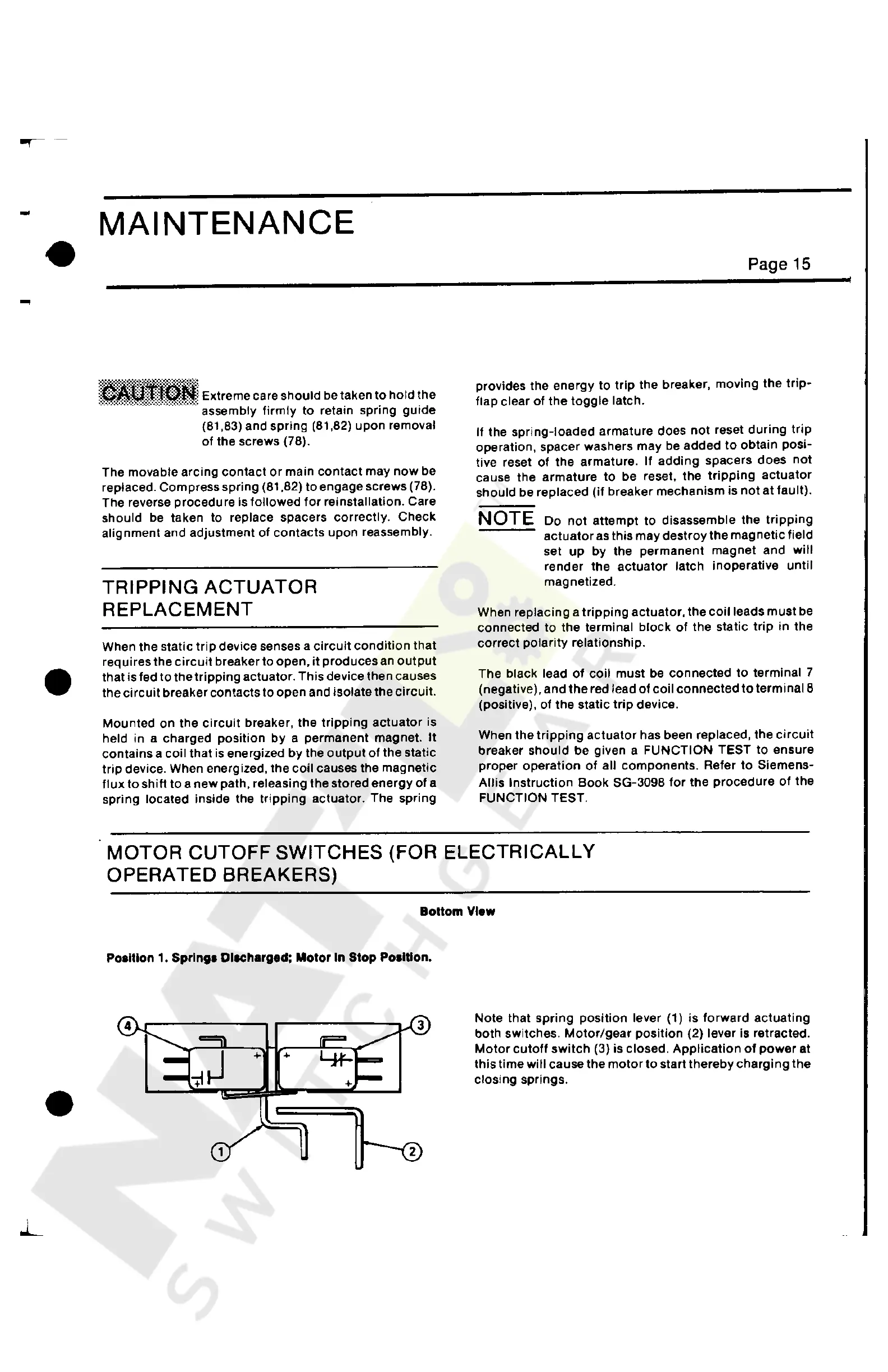
Bottom
View
Position
1.
Springs Dlachargad;
Motor
In
Stop
Position.
+ +
Note that
spring
position lever (1) is
forward
actuating
both switches.
Motor/gear
position
(2) lever is retracted.
Motor
cutoff
switch
(3) is closed.
Application
of
power
at
this time
will
cause
the
motor
to
start
thereby
charging
the
closing
springs
.
Courtesy of NationalSwitchgear.com

 Loading...


