Installing the Device
2.6.1Connecting AC or DC Power
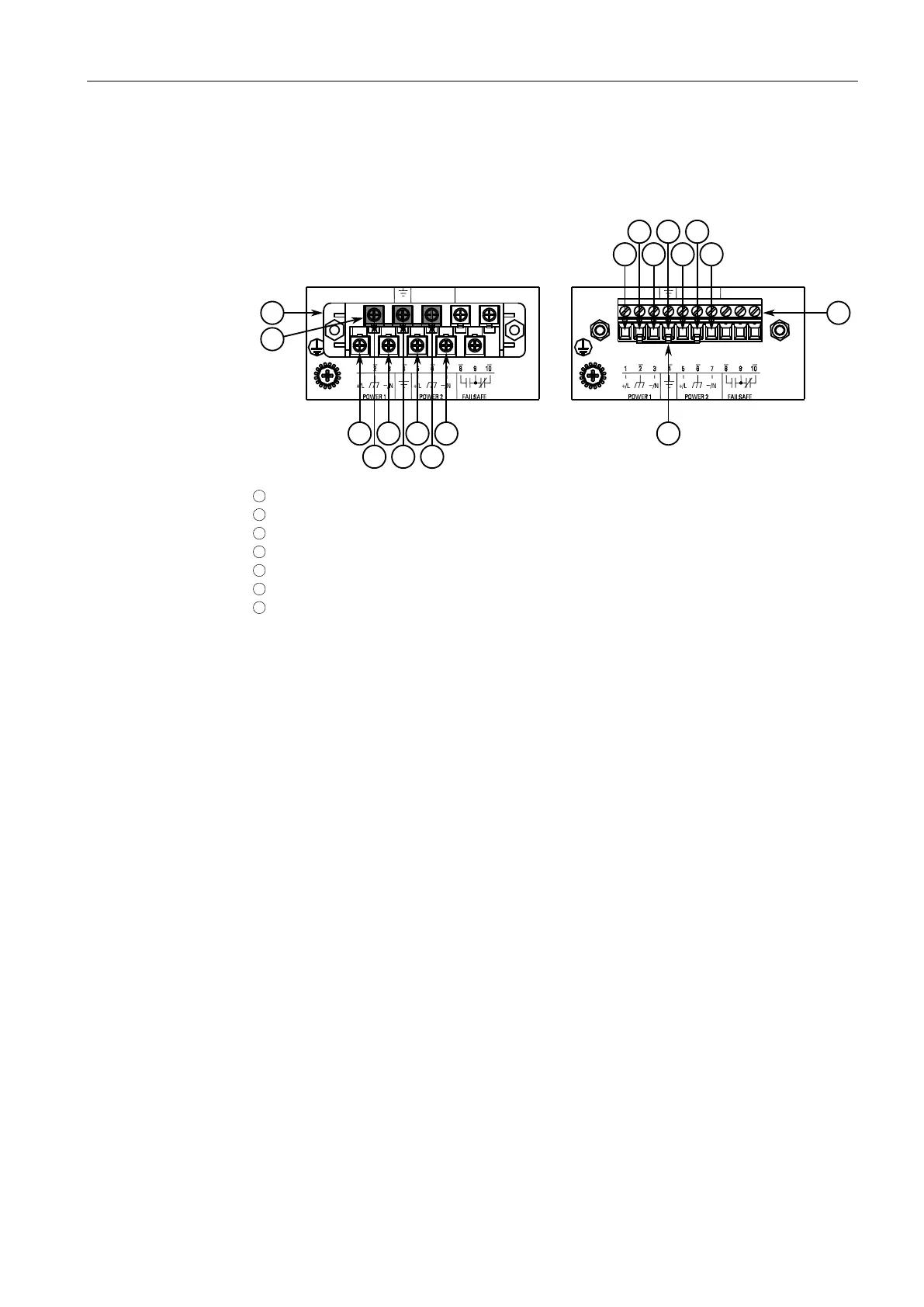
4. Connect the positive wire from the power source to the positive/live (+/L) termi-
nal on the terminal block.
1
Screw-Type Terminal Block
2
Pluggable Terminal Block
3
Jumper
4
Positive/Live (+/L) Terminal
5
Negative/Neutral (-/N) Terminal (-/N)
6
Surge Ground Terminal
7
Chassis Ground Terminal
Figure2.6 Terminal Block Wiring
5. Connect the negative wire from the power source to the negative/neutral (-/N)
terminal on the terminal block.
6. Install the supplied metal jumper between terminals 2, 4 and 6 to connect the
surge ground terminals to the chassis ground terminal. The surge ground termi-
nals are used as the ground conductor for all surge and transient suppression cir-
cuitry internal to the unit.
16
RUGGEDCOM RSG2100
Installation Manual, 03/2020, C79000-G8976-1040-17

 Loading...