Device Management
3
This section describes how to connect to and manage the device.
3.1 Connecting to the Device
The following describes the various methods for accessing the RUGGEDCOM
RSG2100 console and Web interfaces on the device. For more detailed instructions,
refer to the RUGGEDCOM RSG2100 User Guide for the RUGGEDCOM RSG2100.
RS232 Console Port
Connect a workstation directly to the RS232 console port to access the boot-time
control and RUGGEDCOM RSG2100 interfaces. The console port provides access to
RUGGEDCOM RSG2100's console and Web interfaces.
NOTICE
The serial console port is intended to be used only as a temporary connection during
initial configuration or troubleshooting, and should only be used in a safe area (as
defined by IEC 60079-0, Edition 6.0).
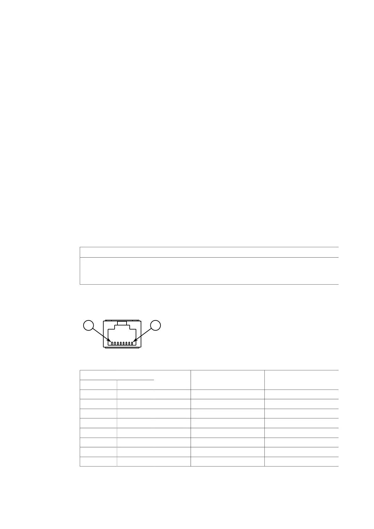
Connection to the console port is made using an RJ45-to-DB9 console cable. The fol-
lowing is the pin-out for the console port:
Figure3.1 RJ45 Console Port Pin Configuration
Pin
RJ45 Male DB9 Female
Name Description Comment
1 6 DSR
a
Data Set Ready
2 1 DCD
a
Carrier Detect Reserved (Do Not Connect)
3 4 DTR
a
Data Terminal Ready
4 5 GND Signal Ground
5 2 RxD Receive Data (to DTE)
6 3 TxD Transmit Data (from DTE)
7 8 CTS
b
Clear to Send
8 7 RTS
b
Read to Send
RUGGEDCOM RSG2100
Installation Manual, 03/2020, C79000-G8976-1040-17
21

 Loading...