Chapter 3
Device Management
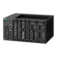
RUGGEDCOM RX1512
Installation Guide
14 Connecting to the Device
Pin
RJ-45 Male
DB9
Female
Name Description
7 8 CTS
b
Clear to Send
8 7 RTS
b
Read to Send
9 RI
c
Ring Indicator
a
The DSR, DCD and DTR pins are connected together internally.
b
The CTS and RTS pins are connected together internally.
c
RI is not connected.
For information about how to connect to the device via the serial console port, refer to the RUGGEDCOM ROX II CLI
User Guide for the RUGGEDCOM RX1512.
For information about how to connect to the device via the management port, refer to either the RUGGEDCOM
ROX II Web Interface User Guide or the RUGGEDCOM ROX II CLI User Guide for the RUGGEDCOM RX1512.
The management port is a 10/100Base-TX copper Ethernet port with an RJ-45 connector. The following is the pin-
out for the management port:
Figure10:RJ-45 Management Port
Pin Name Description
1 RX+ Receive Data+
2 RX- Receive Data-
3 TX+ Transmit Data+
4 Reserved (Do Not Connect)
5 Reserved (Do Not Connect)
6 TX- Transmit Data-
7 Reserved (Do Not Connect)
8 Reserved (Do Not Connect)
Communication Ports
Connect any of the available Ethernet ports on the device to a management switch and access the RUGGEDCOM
ROX II console and Web interfaces via the device's IP address. The factory default IP address for the RUGGEDCOM
RX1512 is https://192.168.0.2 .
For more information about available ports, refer to Chapter4, Modules .
NOTE
Single-mode fiber ports only support Ultra Physical Contact (UPC) cable connectors.
 Loading...