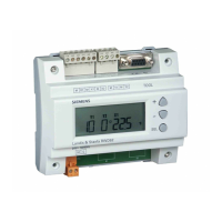
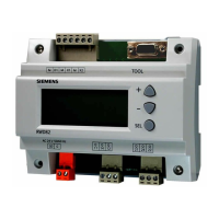
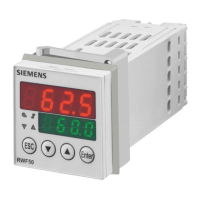
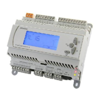
RWD62U Universal Controller Technical Instructions
Document Number 155-737
January 14, 2005
Output
Voltage
Y2
Setpoint
Temp.
Y1
TH0790R1
Figure 6. Two Direct Acting Cool or Two Reverse Acting Cool Sequences
(Application 50 to 59).
Universal Input X1
The primary input for a Siemens Ni 1000 temperature sensor, a Pt 1000 temperature
sensor, or a 0 to 10 Vdc active input.
Universal Input X2
The secondary input for a Siemens Ni 1000 temperature sensor, a Pt 1000
temperature sensor, an active/passive remote setpoint transmitter, or a 0 to 10 Vdc
active input.
Digital Input D1
Selects the day/night changeover. Changeover occurs via potential-free dry contacts
between D1 and M. Typically, a time clock controls D1 input.
Analog Outputs
Each output (Y1, Y2) can be configured for either reverse or direct acting. The
modulating voltage output (Y…) controls the devices requiring a 0 to 10 Vdc signal.
Example
X1
Y2Y1
Temp.
Y
TH0791R1
Figure 7. Constant Volume with Temperature
Control, Direct Acting/Reverse Acting.
X1 Room temperature
Y1 Heating, direct action
Y2 Cooling, reverse action
X1
Y2Y1
Temp.
Y
TH0811R1
Figure 8. Constant Volume with Temperature
Control, Reverse Acting/Direct Acting.
X1 Room temperature
Y1 Heating, reverse action
Y2 Cooling, direct action
Auxiliary Functions
One of the following auxiliary functions can be selected:
• P+I limiter (Absolute, #x2 and Relative, #x3)
• Remote setpoint, #x1
• Cascade control, #x5
• Setpoint compensation, #x4
• Winter/summer operation, Digital #x6, Analog #x7
• Maximum priority, #x8
• Main loop 0 to 10V input, #x9
Day and night operation mode is also available.
Siemens Building Technologies, Inc. Page 5
 Loading...
