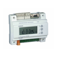
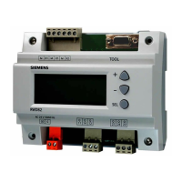
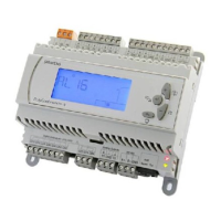
RWD62U Universal Controller Technical Instructions
Document Number 155-737
January 14, 2005
Installation Notes
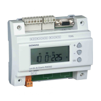
The RWD62U controller can be mounted as follows:
NOTE: Observe all local installation regulations and building codes.
A On a DIN rail at least 4.7 inches (120 mm) long
B Wall-mounted with two #6 screws
C Front-mounted using standard hardware:
• One DIN rail 5.9 inches (150 mm) long
• Two hexagonal blocks 1.97 inches (50 mm)
• Washers and screws
D In the ARG62.21 protective housing
TH0741R1
AB C D
Figure 17. Mounting Options.
Electrical Installation Notes
CAUTION:
• Standard cables can be used for the controller. However, when
mounting in an environment greatly exposed to Electrical Magnetic
Interface (EMI), use only shielded cables.
• The RWD62U is designed for 24 Vac operating voltage.
• Use safety insulating transformers with double insulation; they
must be designed for 100% duty.
• When using several transformers in one system, the connection
terminals G0 (ground) must be galvanically connected.
• Supplying voltages above 24 Vac to low voltage connections may
damage or destroy the controller or any other connected devices.
• Connections to voltages exceeding 24 Vac endanger personal
safety.
• The ARG62.21 Protective Housing does not provide grounding
between conduit connections. Use grounding bushings and jumper
wires or equivalent.
Commissioning Notes
A commissioning booklet is included with the RWD62U controller.
Observe the following:
• The controller must be configured for application-specific operation using the
standard application number.
• Application-specific fine tuning can be performed if required (see the
commissioning booklet).
• Power supply to the controller and the connected devices must be guaranteed.
• Values and settings entered remain available even on power failure.
Siemens Building Technologies, Inc. Page 9
 Loading...
