49 / 60
Siemens Actuators SAS.., SAT.. for valves CE1P4041en
Smart Infrastructure Connection diagrams and dimensions 2019-04-09
SAT31.008
Accessory plug-in space A
-
6.2 Connection terminals
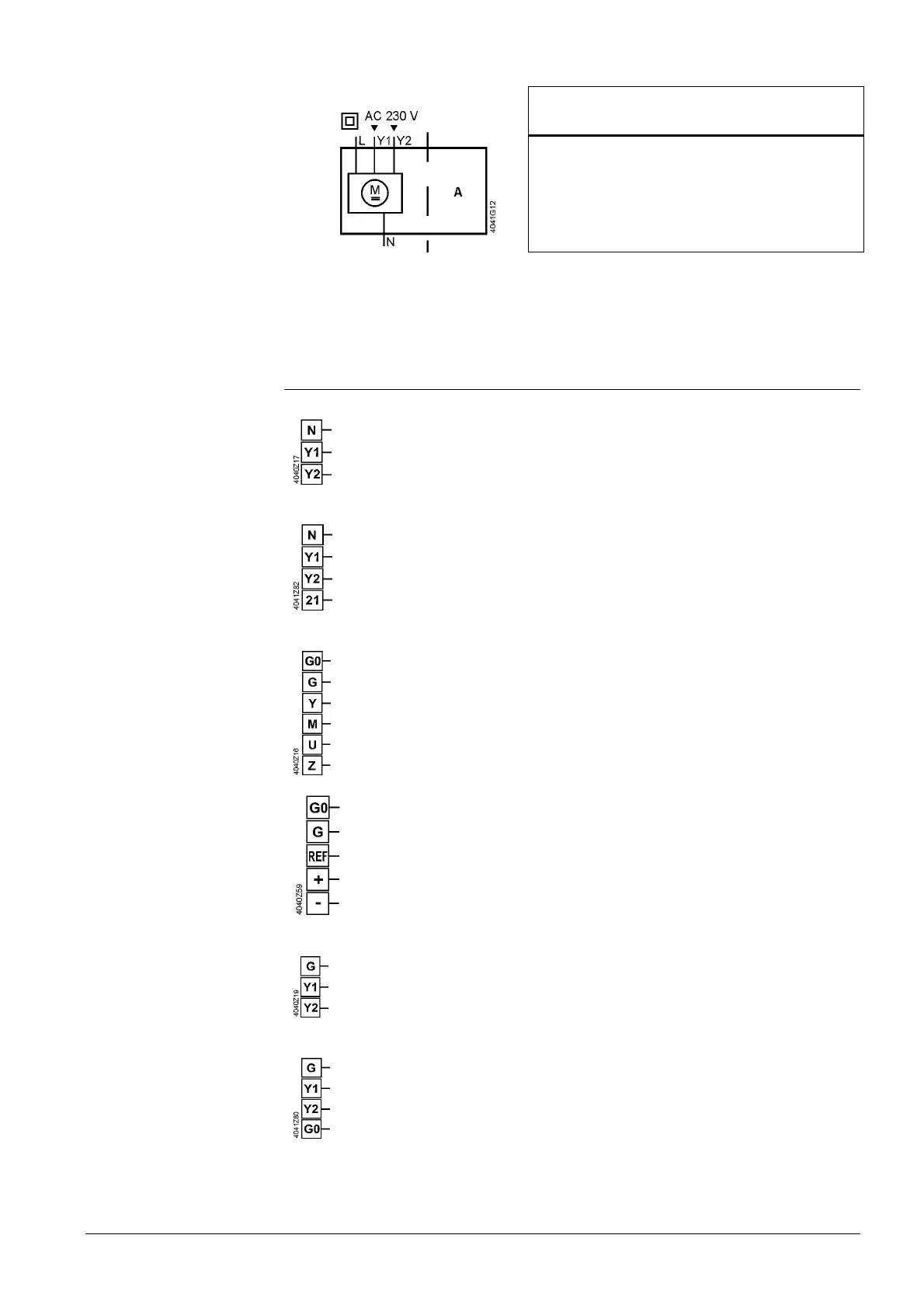
6.2.1 Actuators
AC 230 V, 3-position
System neutral (SN)
Positioning signal (actuator’s stem extends)
Positioning signal (actuator’s stem retracts)
AC 230 V, 3-position
System neutral (SN)
Positioning signal (actuator’s stem extends)
Positioning signal (actuator’s stem retracts)
Fail safe function
AC/DC 24 V, DC 0…10 V / 4…20 mA / 0…1000 Ω
Sytem neutral (SN)
System potential (SP)
Positioning signal for DC 0…10 V / 4…20 mA
Measuring neutral
Position feedback DC 0...10 V
Positioning signal forced control AC/DC ≤ 24 V, 0...1000 Ω
AC/DC 24 V, Modbus RTU connection cable
System neutral (SN)
System potential (SP) AC 24 V ~ / DC 24 V ⎓
Reference (Modbus RTU)
Bus + (Modbus RTU)
Bus - (Modbus RTU)
black
red
violet
grey
pink
AC/DC 24 V, 3-position
System potential (SP)
Positioning signal (actuator’s stem extends)
Positioning signal (actuator’s stem retracts)
AC/DC 24 V, 3-position
System potential (SP)
Positioning signal (actuator’s stem extends)
Positioning signal (actuator’s stem retracts)
System neutral (SN)
SA..31..
(without SAT31.008)
SA..31.5..
SA..61..
SAS61../MO
SA..81..
SAS81.33U
 Loading...