Hardware Design of the PC Adapter USB
PC Adapter USB
4-4 A5E00166353-02
1
2
3
4
5
6
7
8
9
1
2
3
4
5
6
7
8
9
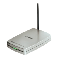
NC
NC
NC
NC
NC
NC
M24V
LTG_B
RTSAS
M5V
P24V
LTG_A
Shield
Shield
9-pin subminiature D 9-pin subminiature D
Fig. 2: MPI cable (0.3 m)
9
8
3
4
6
5
1
2
7
1M
M
+3,15V
+1,95V
5V
USB
MPI
POW ER
USB
Electronics
24V DC
1
2
3
4
M
U
BV1.1 12MBit
s
P5
D-
D+
M5
RTSPG
LTG
A
LTG
B
RTSAS
P5V
M5V
M24V
P24V
Shield
PC
otential area
S
otential area
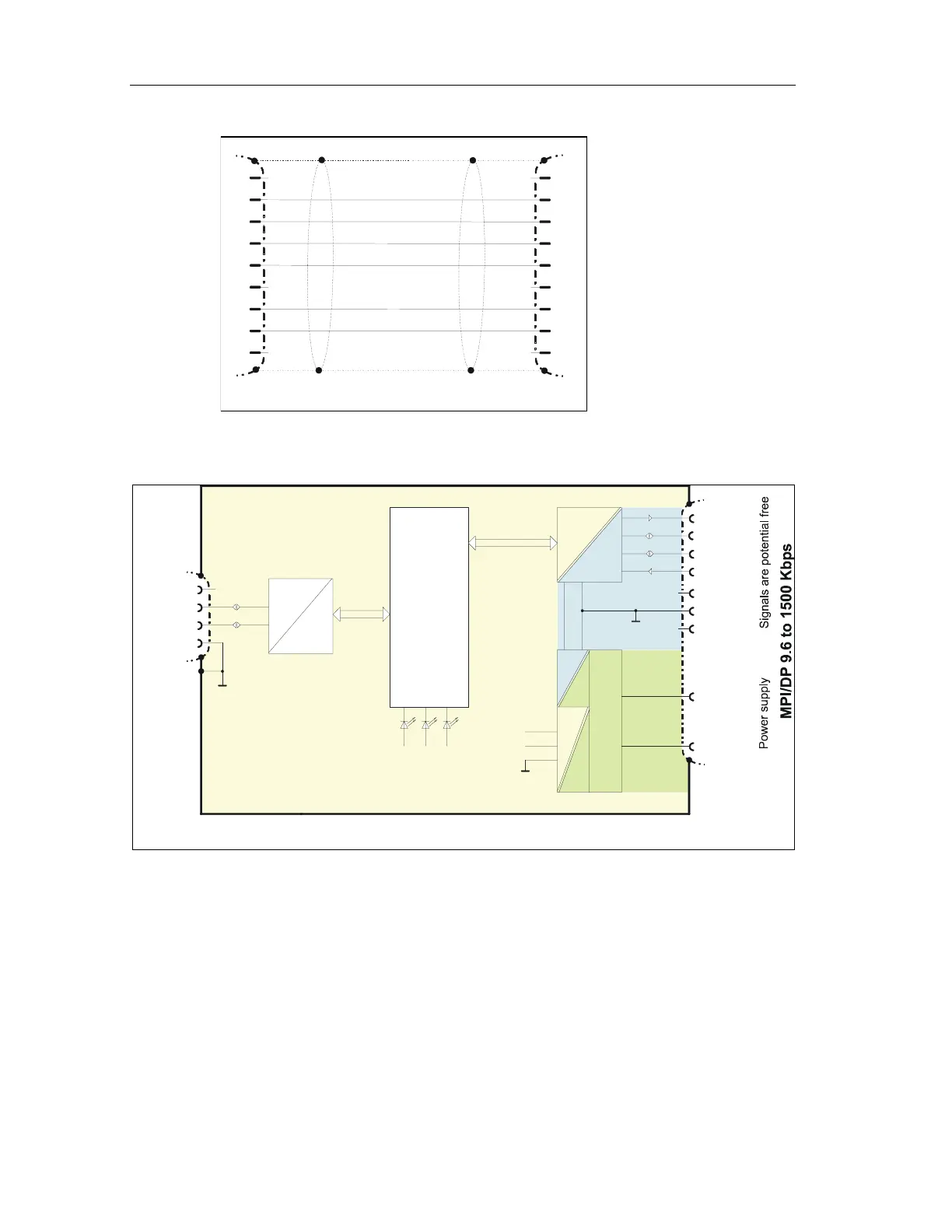
Fig. 3: Block diagram
The MPI/DP and USB interfaces of the PC Adapter USB are electrically isolated
within a safety extra low-voltage circuit (SELV). It can therefore be operated
directly on ungrounded S7/M7/C7 systems.
13.05.2003
3.05.200313.05.200313.05.2003
 Loading...