17-4
TP27, TP37 Equipment Manual
Release 01/00
17.1.2 Connectors and Adjusters
Each DKM board has
S a 10–pin array for connecting the outputs and external voltage supply, and
S a DIL switch for configuring the outputs so that they can be set by the soft-
ware.
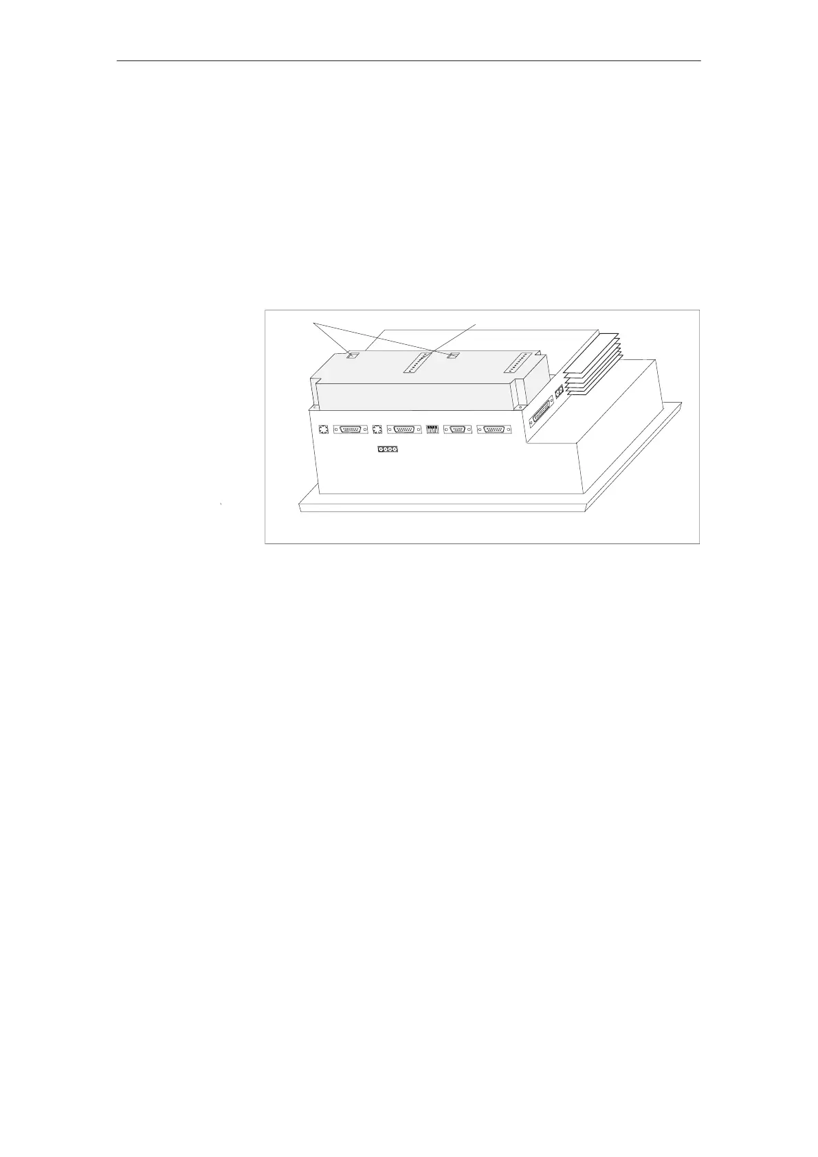
When installed, the pin array and DIL switch are on the rear side of the Touch
Panel (illustrated in an example of the TP37 in figure 17-4).
DKM A
DKM
B
DKM ADKM B
DIL switch
Pins
Figure 17-4 Location of the connection and adjustment elements (example TP37)
Options
 Loading...


