17-8
TP27, TP37 Equipment Manual
Release 01/00
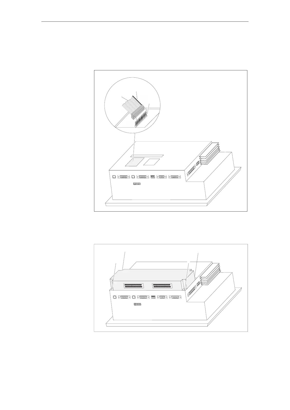
3. Connect the plug of the CPI ribbon cable to the Touch Panel pin array so
that the colored side of the ribbon cable faces in towards the inside of the
unit (illustrated in an example of the TP37 in figure 17-6).
Color coding
Pins
Ribbon
cable
Figure 17-6 Connecting the control panel interface (example: TP37)
4. Secure the control panel interface to the Touch Panel with the four screws
enclosed (illustrated in an example of the TP37 in figure 17-7).
DKM A
DKM
B
Figure 17-7 Securing the control panel interface (example: TP37)
Removal is carried out in the reverse of the installation procedure.
Options