17-10
TP27, TP37 Equipment Manual
Release 01/00
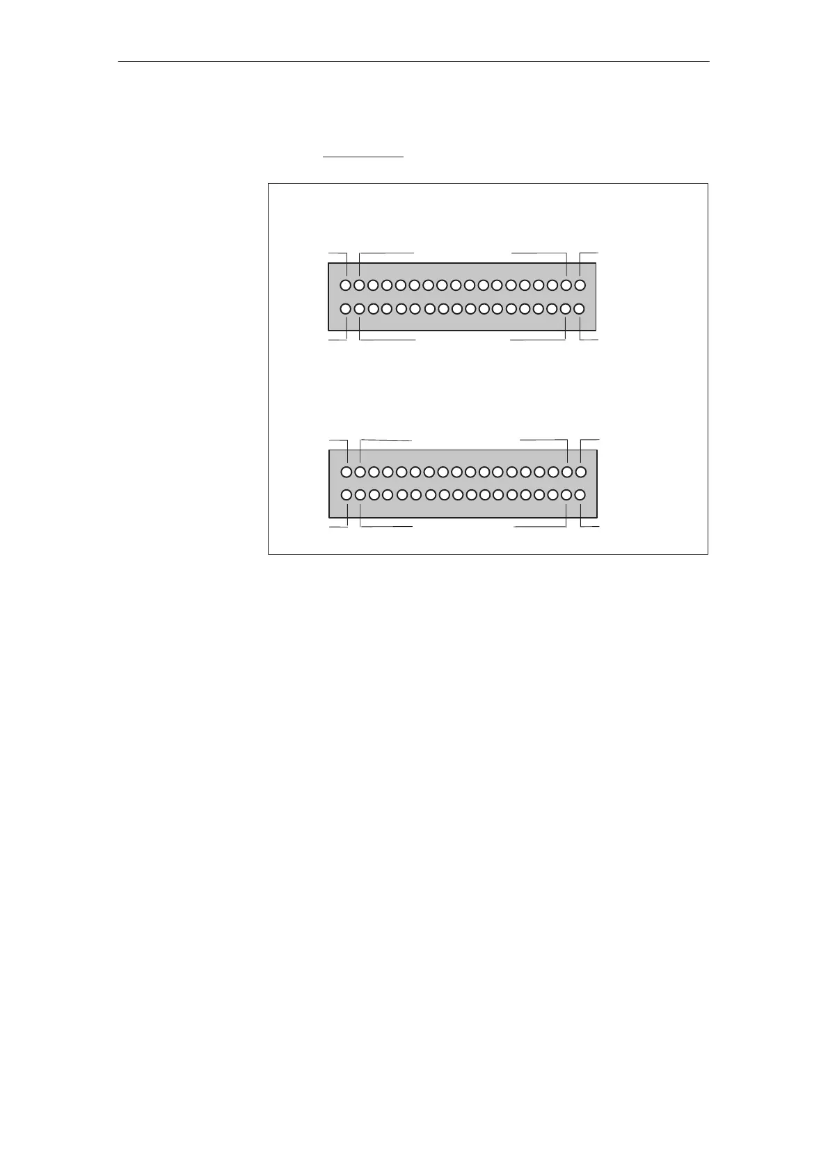
The connectors of module boards CPI 1 und CPI 2 have the following pin as-
signment when installed (see figure 17-8):
+24V DC ext.
GND
1)
DO 16 to DO 1
CPI 1
CPI 2
+24V DC ext.
GND
1)
DI 16 to DI 1
+24V DC ext.
GND
1)
DO 32 to DO 17
+24V DC ext.
GND
1)
DI 32 to DI 17
1)
not isolated
The controls and light indicators to be used are connected by means of the
nine–pin connectors supplied.
S Connect the wires (conductor cross–sections 0.5 ... 2.5 mm2)
S Plug in the terminal blocks on the adapters of the CPI module boards.
Connectors
Options
 Loading...


