18-5
TP27, TP37 Equipment Manual
Release 01/00
Step Action
1
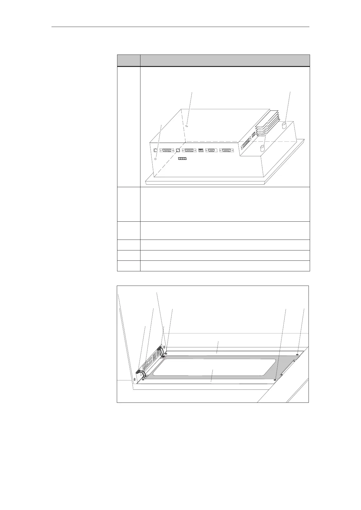
Slacken the two knurled screws ¶ at the rear of the TP and loosen
the two screws at the top and underside.
2 Carefully tilt the hinged rear panel backwards until the plug con-
nections for the ribbon cable and 8–pin socket housing can be re-
moved.
Then tilt the rear panel backwards as far as the stop.
3 Undo two screws per fluorescent tube ® (figure 18-1) and remove
the covers ¯.
4 Remove the two connectors °.
5 Replace the fluorescent tubes.
6 Reassemble in the reverse sequence of the disassembly procedure.
®
¯
°
®
®®
¯
°
Figure 18-1 Replacing the back–lighting
Procedure
Maintenance/Upkeep