A-6
TP27, TP37 Equipment Manual
Release 01/00
Control Panel Interface
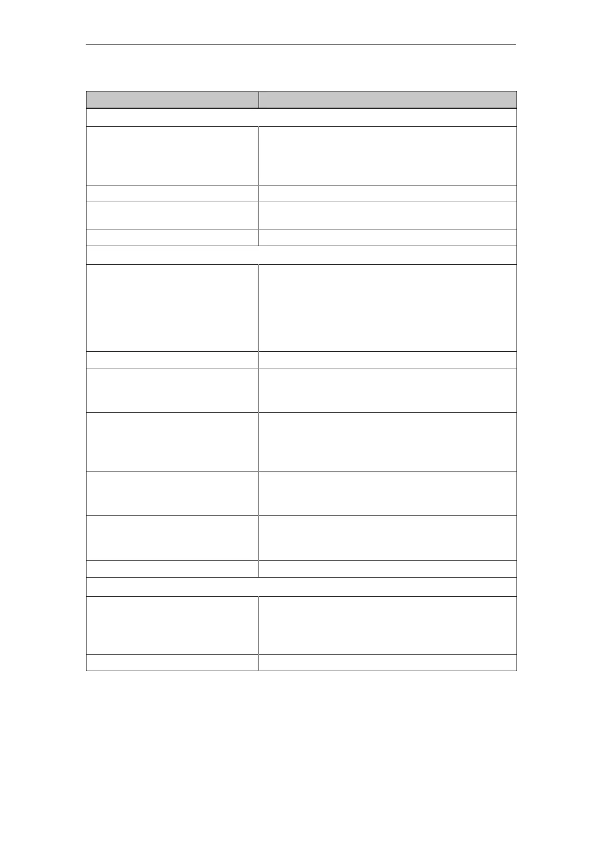
Voltage supply for outputs, load voltage supply and internal logic circuitry
Voltage supply
S rated value
S permissible range
S value at t < 0.5 sec
OP37 24 V DC
+18.0 to +30.0 V
35 V
Power consumption of logic circuitry 40 mA
Short-circuit protection upon polarity rever-
sal of load voltage
4
Connection of Lamps (inductive load not permitted)
Outputs
No. of outputs
S in groups of
S output DO1 to DO4
S output DO5 to DO8
S output DO9 to DO12
S output DO13 to DO16
16
4
Group 1
Group 2
Group 3
Group 4
Optical isolation –
Output voltage
S with signal “0”
S with signal “1”
Max. 2 V (idling)
Min. (voltage supply –3 V)
Output current
S with signal “0”
S with signal “1”
Max. 1 mA
Max. 500 mA per group
1 output of 200 mA, the remainder 100 mA
Switch rate at
S resistive load
S lamp load
Max. 100 Hz
Max. 8 Hz
Load current per group
S aggregate current
S on short-circuit
500 mA
Complete group deenergized
Cable length Max. 1 m
Voltage supply for inputs
Voltage supply
S rated value
S permissible range
S value at t < 0.5 sec
+ 24 V DC
+18.0 to +30.0 V
35 V
Connection of Pushbuttons, switches (inductive load not permitted)
Technical Data
 Loading...


