Overview
1.2 Structure of the devices
IOT2000 Extension Modules
8 Operating Instructions, 2018/05, A5E39456816-AB
Structure of the devices
1.2.1
Structure of SIMATIC IOT2000 Input/Output Module
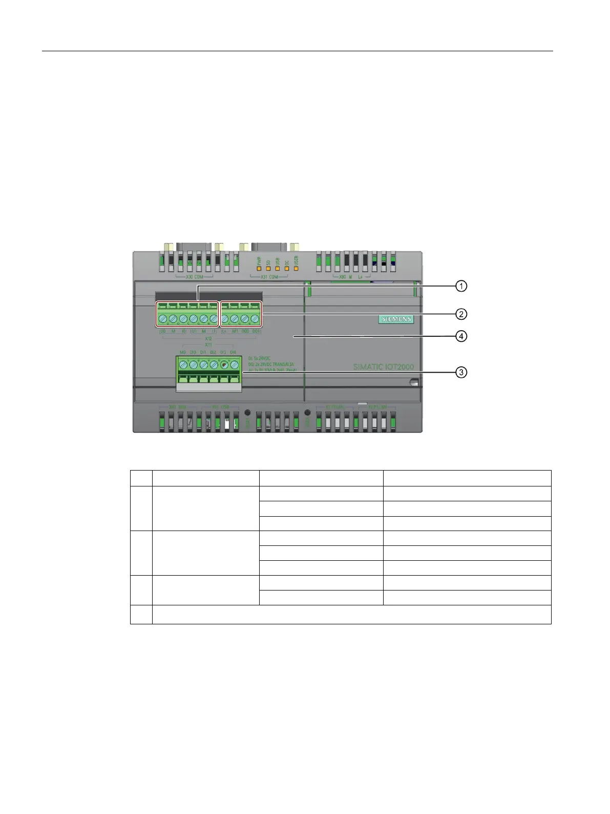
IOT2000 Input/Output Module
The following figure shows the configuration and interfaces of the IOT2000 Input/Output
Module.
Analog interface
1)
Digital output interface
2)
Power supply of digital output
③
Digital input interface
2)
DI1 DI2, DI3, DI4, DI5 Digital input
④
IOT2000 Input/Output Module cover
M is directly connected with the M of Arduino interface and it is not isolated.
M0 and M1 are isolated by optical coupling.
For more information on configuration and interfaces of the SIMATIC IOT2000, see
SIMATIC
IOT2020, SIMATIC IOT2040 Operating Instructions.