PC/TS Adapter Quick Reference Guide
10
PC/TS Adapter
A5E00078070-02
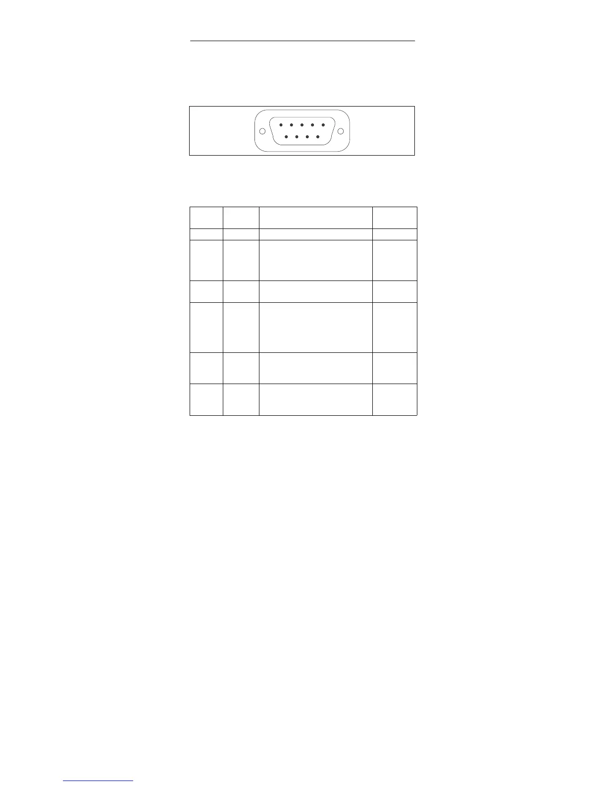
6.3 Pin Configuration
The MPI/DP connector has the following pin configuration:
5
1
9
6
Figure 1-9 MPI/DP Connector
Signals
Pin
No.
Abbre-
viation
Description Input/
Output
1 NC Pin is unassigned -
2 M24V 24 V supply’s 0 V line, sup-
plies adapter electronics via
DC/DC converter (PC
potential area)
Input
3 LTG_B Data line B Input/out-
put
4 RTSAS RTSAS Control signal for
receive data current; the
signal is active ‘1’ when the
directly connected interface
module is transmitting.
Input
5 M5V 5 V supply’s 0 V line,
supplies the adapter’s
S7/M7/C7 potential area
Input
6 P5V 5 V supply’s +5V line,
supplies the adapter’s
S7/M7/C7 potential area
Input