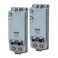
SIMATIC RF185C, RF186C, RF188C, RF186CI, RF188CI
Operating Instructions, 04/2020, C79000-G8976-C512-03
3
1 Introduction ............................................................................................................................................. 7
2 Security recommendations ...................................................................................................................... 9
3 Description ............................................................................................................................................ 15
3.1 Properties of the communications modules ............................................................................ 15
3.2 I/O functions of the CI device versions ................................................................................... 17
3.3 User-specific procedure .......................................................................................................... 17
3.4 Design ..................................................................................................................................... 19
4 Mounting ............................................................................................................................................... 21
4.1 Installation dimensions and position ....................................................................................... 21
4.2 Mounting the communications module ................................................................................... 22
4.3 Use at altitudes over 2,000 m ................................................................................................. 24
5 Connection ........................................................................................................................................... 27
5.1 Network topology .................................................................................................................... 28
5.2 Operation of the CM on grounded/ungrounded power supply ............................................... 30
5.3 Electrical design of the CM ..................................................................................................... 33
5.4 Connecting CM to functional ground ...................................................................................... 36
5.4.1 Mounting the CM on a conductive base ................................................................................. 36
5.4.2 Mounting the CM on a non-conductive base .......................................................................... 38
5.5 Connecting the communications module ................................................................................ 40
5.6 Supply voltage and PROFINET IO loop-through .................................................................... 45
5.7 Effect of cable length on the supply voltage ........................................................................... 46
6 Configuring ........................................................................................................................................... 47
6.1 Assign the IP address / device name ..................................................................................... 47
6.1.1 Assigning the IP address / device name with STEP 7 ............................................................ 47
6.1.2 Assigning the IP address / device name with SINEC PNI ...................................................... 50
6.1.3 Assigning an IP address via DHCP ........................................................................................ 51
6.2 Configuration via PROFINET IO ............................................................................................. 52
6.3 Configuration via XML............................................................................................................. 59
6.4 Configuration via OPC UA ...................................................................................................... 59
6.5 Configuring with Studio 5000 Logix Designer ......................................................................... 60
7 Configuring with the WBM ..................................................................................................................... 61
7.1 Starting WBM .......................................................................................................................... 61
7.2 The WBM ................................................................................................................................ 63