Product overview
2.5 Operator controls and display elements
CPU 1513R-1 PN (6ES7513-1RL00-0AB0)
Equipment Manual, 05/2021, A5E42009333-AC
23
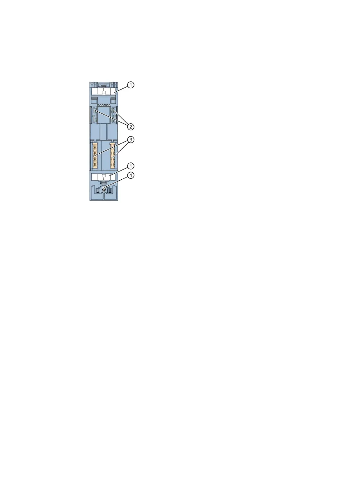
2.5.3 Rear view of the CPU
The figure below shows the connection elements on the rear of the CPU 1513R-1 PN.
Plug-in connection for power supply
Plug-in connection for backplane bus
Figure 2-6 View of the CPU 1513R-1 PN - rear

 Loading...


