Connecting
3.1 Terminal assignment
CPU 1513R-1 PN (6ES7513-1RL00-0AB0)
Equipment Manual, 05/2021, A5E42009333-AC
27
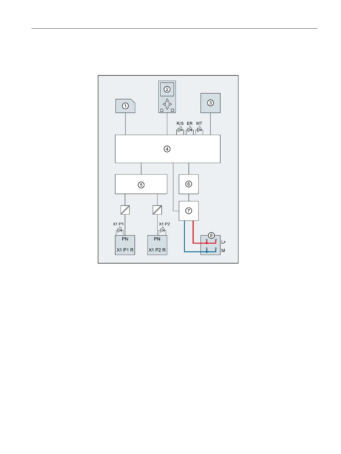
Block diagram
The following figure shows the block diagram of the CPU 1513R-1 PN.
SIMATIC memory card (X50)
PROFINET interface X1 port 1
PROFINET interface X1 port 2
Mode selector RUN/STOP/MRES
RUN/STOP LED (yellow/green)
Backplane bus connection
(connection to backplane bus not configurable)
Supply of the 24 V DC supply voltage (X80)
Figure 3-2 Block diagram of the CPU 1513R-1 PN

 Loading...


