Technical data of CPU 31xC
6.6 Technical data of the integrated I/O
CPU 31xC and CPU 31x, Technical data
6-34 Manual, Edition 08/2004, A5E00105475-05
6.6.2 Analog I/O
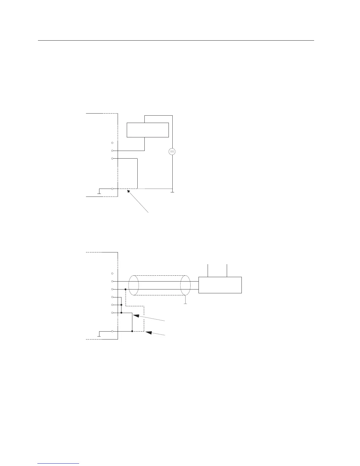
Wiring of the current/voltage inputs
The figure below shows the wiring diagram of the current/voltage inputs operated with
2-/4-wire measuring transducers.
2-wire
signal converter
AI2
AI2
AI2
u
I
c
8
9
10
M
M
ANA
20
We recommend connecting AIx
C
with M
ANA
using a bridge.
+
-
+
+24V
-
Al
0
: Pin 2 to 4
AI
1
: Pin 5 to 7
Al
2
: Pin 8 to 10
Al
3
: Pin 11 to 13
Figure 6-1 Connection of a 2-wire measuring transducer to an analog current/voltage input of
CPU 313C/314C-2
4-wire
signal converter
AI : Pin 2 to 4
AI : Pin 5 to 7
AI : Pin 8 to 10
AI : Pin 11 to 13
0
1
2
3
L+
AI2
AI2
AI2
AI3
AI3
AI3
u
I
c
u
I
c
8
9
10
11
12
13
M
ANA
20
M
M
+
-
+
-
Short-circuit non-wired input channels
and connect Alx
C
with M
ANA
.
We recommend connecting Alx
C
with M
ANA
when using the 4-wire signal converter.
Figure 6-2 Connection of a 4-wire measuring transducer to an analog current/voltage input of
CPU 313C/314C-2

 Loading...


