Configuring Input/Output Data Areas
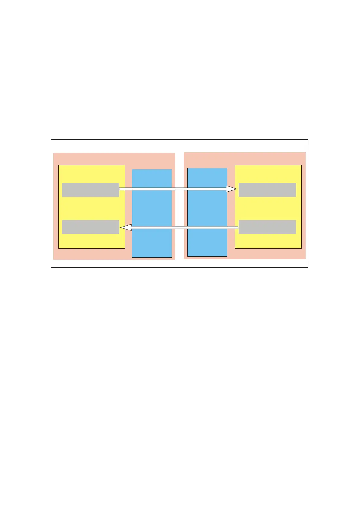
You must configure both an output data area and an input data area in HW Config
for each communication connection between two F-CPUs. In the figure below,
each of the two F-CPUs is supposed to be able to send and receive data. You
must therefore configure two output data areas and two input data areas for each
F-CPU.
You assign the configured start addresses of the input and output data areas to the
LADDR parameter of the corresponding
F-application blocks F_SENDDP and F_RCVDP in the safety programs (see
manual, Section 5.4).
F-CPU 1
F_SENDDP: LADDR 16
F_ RCVDP: LADDR 28
F_RCVDP: LADDR 18
F-CPU 2
Safety Program Safety Program
HW Config HW Config
I Addr. 16
Length 6 bytes
O Addr. 16
Length 12 bytes
O Addr. 28
Length 6 bytes
I Addr. 28
Length 12 bytes
O Addr. 18
Length 6 bytes
I Addr. 18
Length 12 bytes
I Addr. 30
Length 6 bytes
O Addr. 30
Length 12 bytes
F_SENDDP: LADDR 30
DP Master DP Slave
Rules for Defining the Data Areas
The output data area for the data to be sent must begin with the same start
address as the associated input data area. A total of 12 bytes (consistent) must be
configured for the output data area, and 6 bytes (consistent) for the input data
area.
The input data area for the data to be received must begin with the same start
address as the associated output data area. A total of 12 bytes (consistent) must
be configured for the output data area, and 6 bytes (consistent) for the input data
area.
Product Information for the S7 Distributed Safety, Configuring and Programming Manual
8 A5E00169432-02

 Loading...


