Mounting, wiring, connecting, system interfaces, configuration guidelines
12.2 Wiring, connecting
SIMOCODE pro
System Manual, 05/2019, A5E40507475002A/RS-AD/004
207
Sequence for wiring the removable terminals for SIMOCODE pro V PN / pro V EIP / pro V PN GP
basic units
Proceed as follows:
Table 12- 11 Wiring the removable terminals of the basic unit
Connect the cables to the upper and lower terminals.
2 Connect the equipment shield to the SPE
1)
terminal.
1)
pro via terminal SPE with the maximum possible cross-section and
with as short a cable as possible to the functional ground of the control cabinet, e.g. to the
grounded mount
ing plate of the control cabinet.
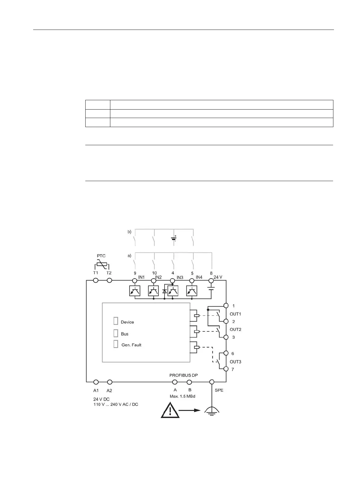
Connection examples of SIMOCODE pro C/V/S basic units
Figure 12-16 Connection example of SIMOCODE pro C/V basic units