Supplementary system components
6.5 CBE30 communication board Ethernet
SIMOTION D4x5
106 Manual, 02/2012
Position of the ports
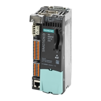
The interfaces are located on the front side of the CBE30.
Figure 6-11 CBE30 interface
6.5.4.2 LED displays
Position of the LEDs
The X1400 interface with the four ports has integrated LEDs for displaying the link and the
activity for each port. The front panel of the board is also fitted with two LEDs (Fault and
Sync), which indicate the bus status.
Table 6- 30 Meaning of the LED displays
LED Meaning
link ... indicates whether a different device is connected to port x and a physical
connection exists
Activity ... indicates whether data is being received or sent at port x
Sync ... indicates the synchronization status of the PROFINET IO interface
Fault ... indicates a fault state of the PROFINET IO interface
Additional references
Detailed information on the states of the status LEDs can be found in
SIMOTION D4x5
Commissioning and Hardware Installation Manual, Diagnostics chapter.

 Loading...


