Supplementary system components
6.4 Controller Extension CX32
SIMOTION D4x5
Manual, 02/2012
93
Position of the connector
The X122 connection is on the front side of the CX32 at the top, see appropriate figure in
Chapter Overview of interfaces (Page 90).
Conne
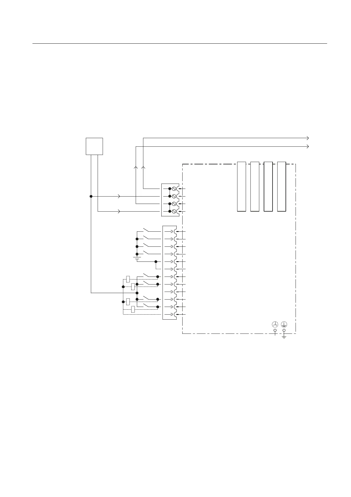
ction and block diagram
The following figure shows the schematic diagram and the connection of the digital
inputs/outputs on the CX32 and the associated external power supply.
&;FRQWUROOHUH[WHQVLRQ
'5,9(&/L4VRFNHW
'5,9(&/L4VRFNHW
'5,9(&/L4VRFNHW
'5,9(&/L4VRFNHW
-XPSHURSHQHOHFWULFDO
LVRODWLRQIRUGLJLWDOLQSXWV',
&DQEHLQGLYLGXDOO\
SDUDPHWHUL]HGDV
LQSXWRXWSXW
H[W
9
0
0
',
',
',
',
0
0
','2
','2
','2
','2
0
0
9
0
0
0
0
;
;
;;;;
Figure 6-7 CX32 digital inputs/outputs connection diagram

 Loading...


