Representatio
n
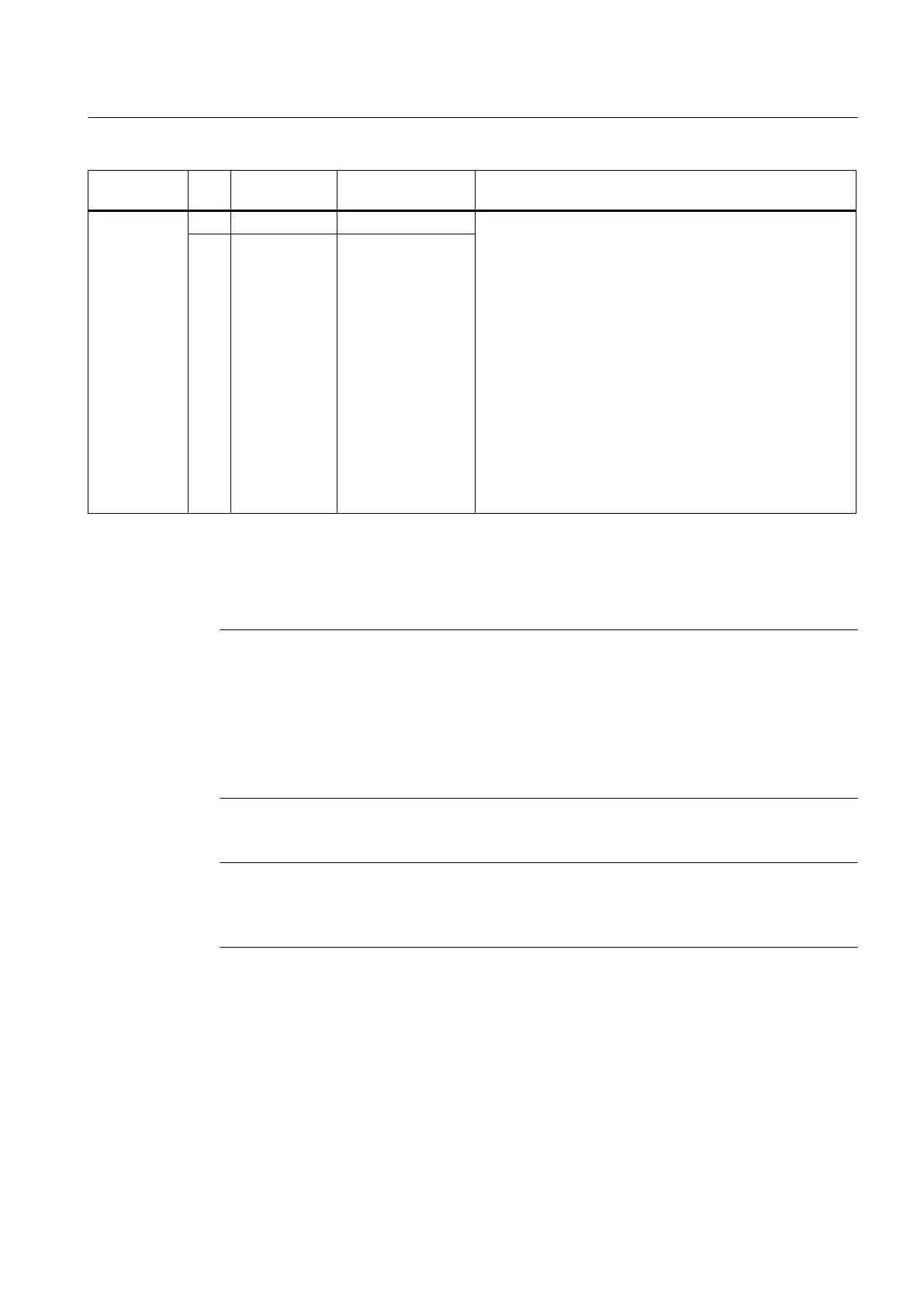
Pin Designation
1)
Notes Technical details
11 DI/DO 11 fast DI/DO
– 0 → 1 signal: 5 μs
–
1 → 0 signal: 50 μs
As output:
● Voltage: 24 V DC
● Max. load current per output: 500 mA
● sustained short-circuit proof
● Output delay, typ./max. (hardware)
3)
:
– 0 → 1 signal: 150 μs / 400 μs
– 1 → 0 signal: 75 μs / 100 μs
12 G
1)
DI: digital input; DI/DO: bidirectional digital input/output; G: electronic ground; G1: reference ground
2)
The rapid inputs can be used as probe inputs or as inputs for the external zero mark
3)
Data for V
cc
= 24 V; load 48 Ω; high ("1") = 90% V
out
; low ("0") = 10% V
out
Note
An open input is interpreted as "low".
The
G1 terminal must be connected for the digital inputs (DI) 0 to 3 to function. The following
options are available:
● Connect the carried digital input reference ground to M1.
● Create a bridge between terminal G and terminal G1 (Important: This will cancel the
electrical isolation for these digital inputs!)
Note
If digital outputs are used, an external 24 V supply is required across terminal X124.
If the 24 V supply is briefly interrupted, the digital outputs are deactivated for this time.
Interfaces
4.2 Digital inputs/outputs
SIMOTION D410
Manual, 04/2014 43
 Loading...


