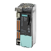
Interfaces
The SIMOTION D410 PN interfaces are described in the following tables.
Table 2-6
SIMOTION D410 interfaces
Interface Description
Digital inputs/outputs
X121
12-pin Mini Combicon:
●
4 digital inputs: for connecting switches and proximity sensors
● 4 digital inputs/outputs: for connecting actuators and sensors
DRIVE-CLiQ interface
X100
8-pin RJ45plus socket to connect DRIVE-CLiQ nodes
PROFINET interface
(ports X200 and X201)
8-pin RJ45 socket to connect to PROFINET
Power Module Interface
(PM-IF)
8-pin direct connector to connect to a Power Module in blocksize
format
Encoder interface (HTL / TTL /
SSI)
X23
15-pin SUB-D socket for connecting HTL, TTL and SSI encoders.
EP terminals/temperature
sensor connection
X120
8-pin Mini Combicon for connecting Safety Integrated input
terminals or for connecting temperature sensing via KTY or PTC
Power supply connection
X124
4-pin screw terminal connection to connect the 24 V DC load power
supply
Measuring sockets
T0, T1, T2 and M
Sockets to output analog signals
Type plates
The figure below shows all the information included on the type plate located on the side of
the unit.
0RGXOHGHVLJQDWLRQ
2UGHU1R
6HULDOQXPEHU
+DUGZDUHUHYLVLRQOHYHO
Figure 2-6 SIMOTION D410 PN type plate
Description
2.4 SIMOTION D410 PN display
SIMOTION D410
30 Manual, 04/2014
 Loading...


