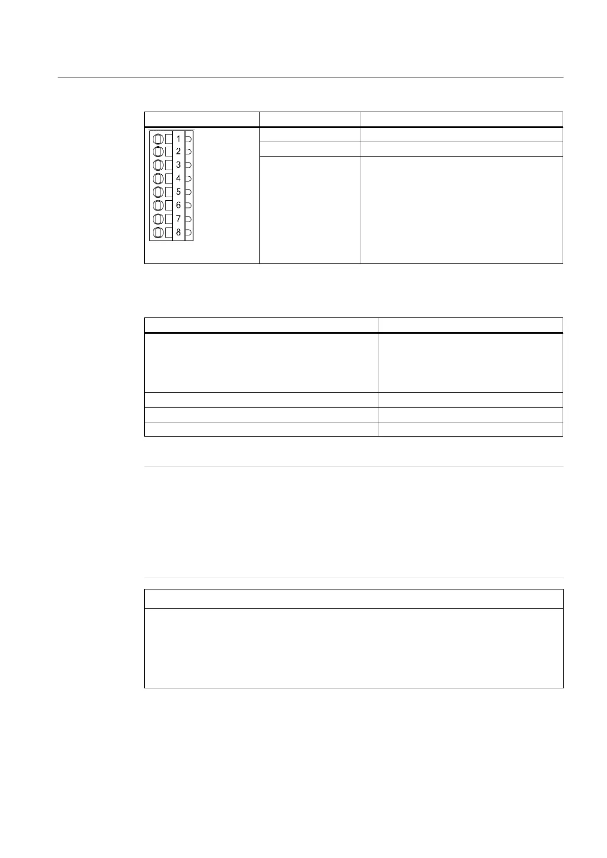
Terminal Designation
1)
6 AO 0-
7 AO 1+
8 AO 1-
Table 7-9
X482 wiring
Features Type
Connectable conductor types
- Rigid
- Flexible
- Flexible with end sleeve, without plastic sleeve
- AWG/kcmil
Conductor cross-section
0.14 mm
2
to 0.5 mm
2
0.14 mm
2
to 0.5 mm
2
0.25 mm
2
to 0.5 mm
2
26 to 20
Stripped length 8 to 9 mm
Tool Screwdriver 0.4 x 2.0 mm
Max. cable length 30 m
Note
An open input is interpreted as approximately "0 V."
The power supply of the analog I/Os of the TB30 is via the option slot of the D4x5‑2 control
unit and not via X424.
The shield is connected to the Control Unit. For more information on "Establishing a shield
connection", see the
SIMOTION D4x5-2
Commissioning and Hardware Installation Manual,
Chapter "Connecting I/Os."
NOTICE
Incorrect results of analog-to-digital conversion due to impermissible input voltage
The common mode range must not be violated.
Makes
sure that the analog input voltage signals can have a maximum voltage of ±30 V with
respect to the reference potential. If the range is infringed, incorrect results may occur during
analog/digital conversion.
Supplementary system components
7.3 TB30 terminal board
SIMOTION D4x5-2
Manual, 04/2014 107