Position of the connector
The X122 connection is on the front side of the CX32‑2 at the top, see appropriate figure in
Section Overview of interfaces
(Page 118).
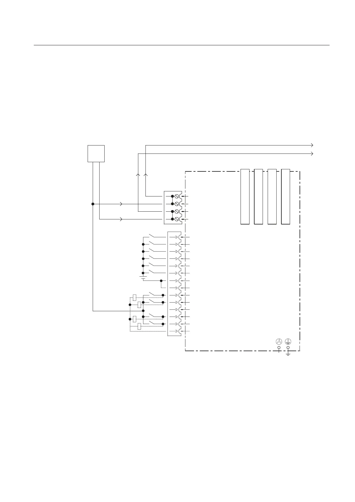
Connection and circuit diagram
The following figure shows the schematic diagram and the connection of the digital I/Os on
the CX32‑2 and the associated external power supply.
-XPSHURSHQHOHFWULFDO
LVRODWLRQIRUGLJLWDOLQSXWV',
&DQEHLQGLYLGXDOO\
SDUDPHWHUL]HGDVLQSXWRXWSXW
([W
&;FRQWUROOHUH[WHQVLRQ
0
0
','2
','2
','2
0
0
',
',
',
',
','2
;
',
',
;;;;
;
0
0
0
0
9
0
0
9
'5,9(&/L4%XFKVH
'5,9(&/L4%XFKVH
'5,9(&/L4%XFKVH
'5,9(&/L4%XFKVH
Figure 7-13 Digital I/Os connection diagram
Supplementary system components
7.5 CX32-2 controller extension
SIMOTION D4x5-2
Manual, 04/2014 121