Representati
on
Pin Name Signal type Description
6 RXN Input Ethernet receive differential signal
7 -- 7 together with 8 via 75•ohm at the 1•nF
capacitor to the shield ground
8 -- 7 together with 8 via 75 ohm at the 1-nF
capacitor to the shield ground
Screened
backshell
M_EXT Screen, permanently connected
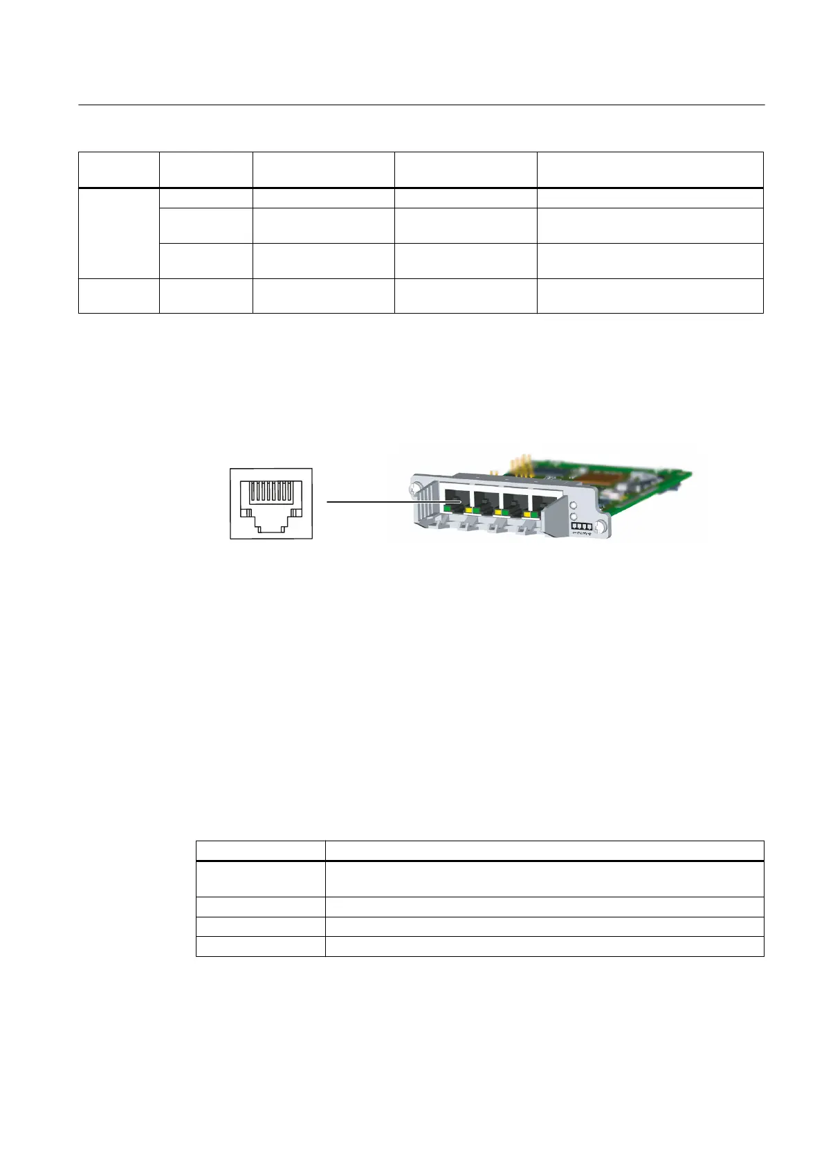
Position of the ports
The interfaces are located on the front side of the CBE30‑2.
Figure 7-10 CBE30‑2 interface
7.4.5
LED displays
Position of the LEDs
The X1400 interface with the four ports has integrated LEDs for displaying the link and the
activity for each port. The front panel of the board is also fitted with two LEDs (Fault and Sync),
which indicate the bus status.
Table 7-15 Meaning of the LED displays
LED Meaning
link ... indicates whether a different device is connected to port x and a physical
connection exists
Activity ... indicates whether data is being received or sent at port x
Sync ... indicates the synchronization status of the PROFINET IO interface
Fault ... indicates a fault state of the PROFINET IO interface
Supplementary system components
7.4 CBE30-2 Ethernet communication board
SIMOTION D4x5-2
Manual, 04/2014 113