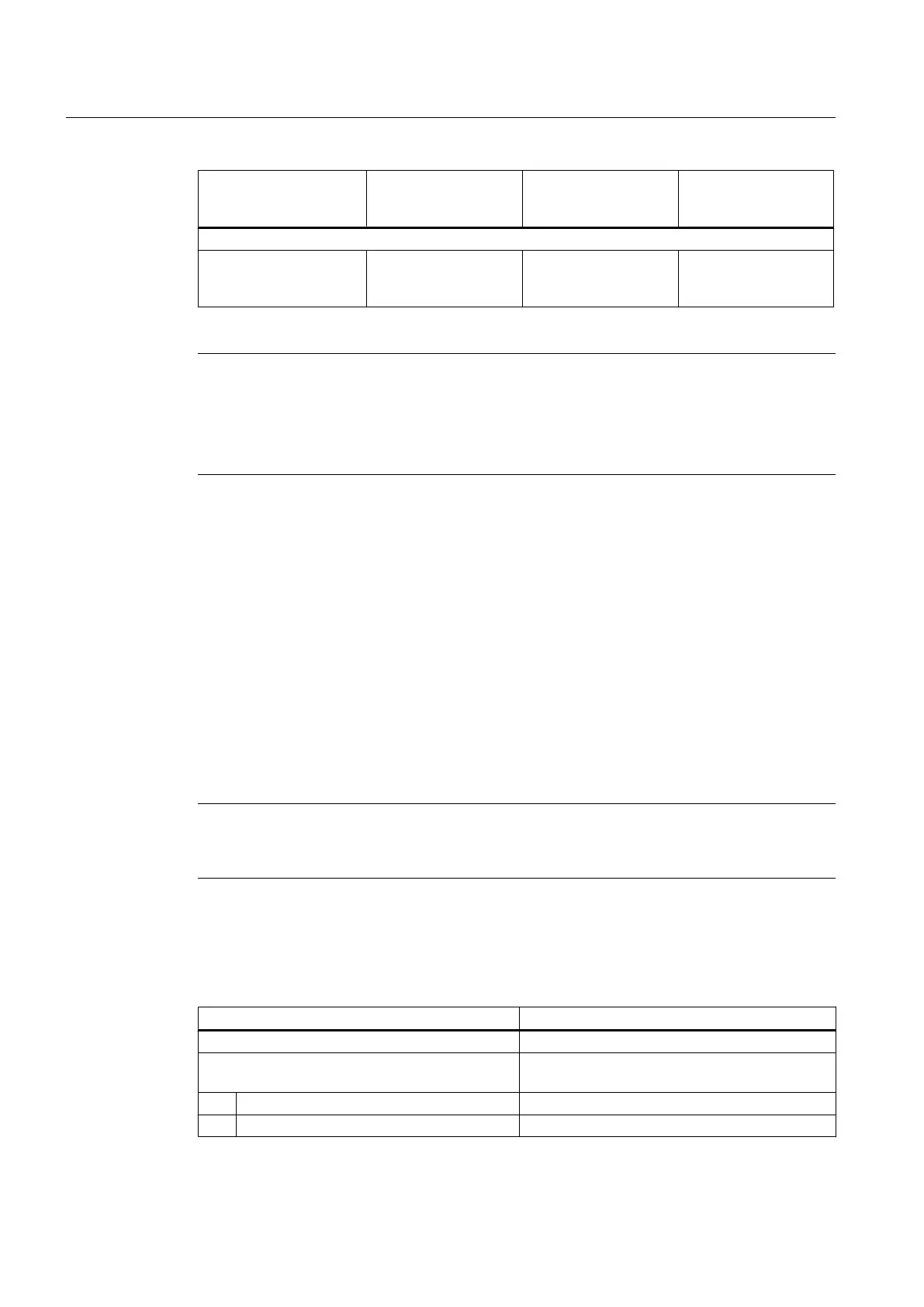
DI 0-7, DI 17, DI 18,
DI 20, DI 21 (X122,
X132)
DI/DO 8-15
(X122, X132)
IN/OUT 0-7
(X142)
Configuration:
Assignment Can be configured
channel-by-channel
on
the drive
Can be configured
channel-by-channel on
the drive
Can be configured
channel-by-channel in
HW Config
Note
For optimal noise immunity of the digital inputs, the use of shielded cables is necessary if
they are to be used as
●
Inputs of measuring inputs or
● Inputs for the external zero mark
Additional references
For
information on configuring the digital I/Os as freely addressable I/Os, inputs of measuring
inputs or outputs of output cams, see the
SIMOTION D4x5‑2
Commissioning and Hardware
Installation Manual.
For information on the configuration and function of the measuring input, output cam, and cam
track technology objects, refer to the
SIMOTION Output Cams and Measuring Inputs
Function
Manual.
4.5 Power supply
This interface is provided for connection of the external power supply.
Note
When using external power supplies (e.g. SITOP), the ground potential must be connected
with the protective ground terminal (PELV).
Features of the interface
Table 4-12
Interface X124
Features Type
Connector type 4-way screw-type terminal
Connectable cable types and conductor cross-
sections
Rigid 0.2 mm² … 2.5 mm²
Flexible 0.2 mm² … 2.5 mm²
Interfaces
4.5 Power supply
SIMOTION D4x5-2
64 Manual, 04/2014