Configuration
3.3 Dimensioning
General Section for Synchronous Motors
Configuration Manual, (PJAL), 11.2005 Edition, 6SN1 197-0AD07-0BP4
3-11
The average motor speed is calculated as follows:
H
t
L
PRWN(PRWN$
PRWDYHUDJH
t
nn
n
•
2
+
=
J
M
Motor moment of inertia
J
G
Gearbox moment of inertia
J
load
Load moment of inertia
N
load
Load speed
i Gear ratio
η
G
Gearbox efficiency
M
load
Load torque
M
R
Friction torque
T Cycle time, clock cycle time
I;F Initial value, final value in time slice Δ
t
k
t
e
Power-on duration
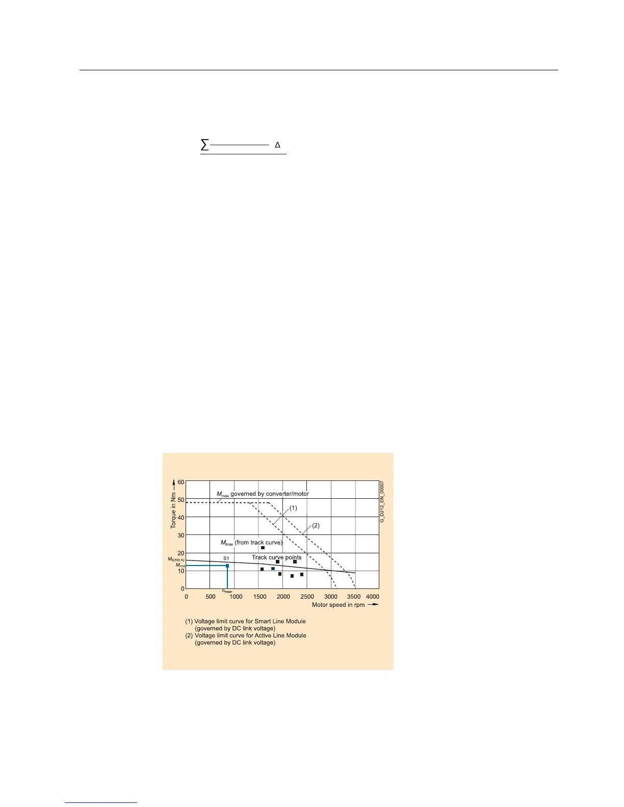
The rms torque M
rms
must lie below the S1 curve.
The maximum torque M
max
is required when the drive is accelerating and for synchronous
motors must lie below the voltage limiting curve and for induction motors below the stability
limit.
In summary, the motor is selected as follows:
Figure 3-7 Selecting motors depending on the load duty cycle (example)
 Loading...


