Motor Components
5
5.1
5.1
Influence of the mounting type and mounted components
Some of the motor power loss is dissipated through the flange when the motor is connected
to the mounting flange.
Non-thermally insulated mounting
The following mounting conditions apply for the specified motor data:
Table 5-1 Non-thermally insulated mounting conditions
Shaft height Steel plate
width x height x thickness
Mounting surface
[m
2
]
28 to 48 120 x 100 x 40 0.012
63 to 160 450 x 370 x 30 0.17
For larger mounting surfaces, the heat dissipation conditions improve.
Thermally insulated mounting without additionally mounted components
For naturally-ventilated and force-ventilated motors, the motor torque must be reduced by
between 5 % and 10 %. We recommend that the motor is engineered using the M
0
(60 K)
values.
0
0.
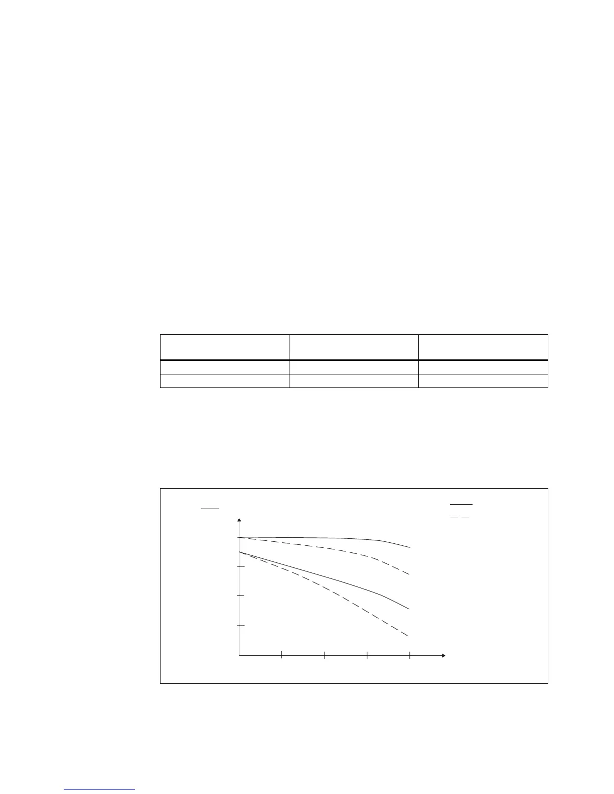
,QVXODWHGPRXQWLQJ
ZLWKRXWJHDUER[
ZLWKJHDUER[
DSSUR[WR
1RQLQVXODWHGPRXQWLQJ
Q1
Q
Figure 5-1 S1 characteristics
General Section for Synchronous Motors
Configuration Manual, (PJAL), 11.2005 Edition, 6SN1 197-0AD07-0BP4
5-1
 Loading...


