Motor Components
5.4 Holding brake
)&LUFXLWEUHDNHU
.&RQWDFWRU
6+ROGLQJEUDNH
59DULVWRU
5
0RWRU
9
)
.
6
*1'
Figure 5-4 Recommended circuit for the external power supply with protective circuit
Table 5-2 Example: Electronic components for the recommended circuit
Electr.
component
Examples
F 3RV10 circuit-breaker with current
paths connected in series. (if
required with mounted auxiliary
contact 3RV1901 to provide a
feedback signal for the drive)
or Miniature circuit-breaker
5SX21. (if required with mounted
auxiliary contact to provide a feedback
signal for the drive)
K1 Auxiliary contactor 3RH11 or Contactor 3RT10
R2 Varistor
SIOVS14K30 (EPCOS)
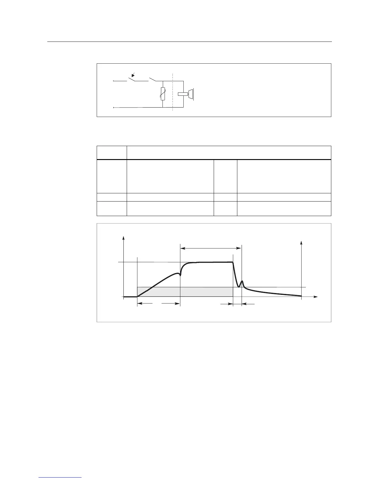
&XUUHQW,
W
,
9ROWDJH9
W
W
%UDNHRSHQHG
9
W RSHQLQJWLPH
W FORVLQJWLPH
PHDVXUHGDW9 9
F
F
Figure 5-5 Terminology (time) for holding operation
Important information and instructions when installing the connecting cable
The brake connecting cable is included in the power cable. The insulation between the
power and brake connection is dimensioned for the basic insulation (VDE 600 V/1000V UL).
The relay K1, located between the coil and contact, must also have basic insulation in order
to protect the internal logic voltage (PELV=Protective Extra Low Voltage). The PELV supply
may not be used to supply the holding brake (refer to the Fig. "Recommended circuit for the
external power supply with protective circuit").
General Section for Synchronous Motors
Configuration Manual, (PJAL), 11.2005 Edition, 6SN1 197-0AD07-0BP4
5-9
 Loading...


