10.99 Parameterization
Siemens AG 6SE7087-6KP50
SIMOVERT MASTERDRIVES Operating Instructions 8-13
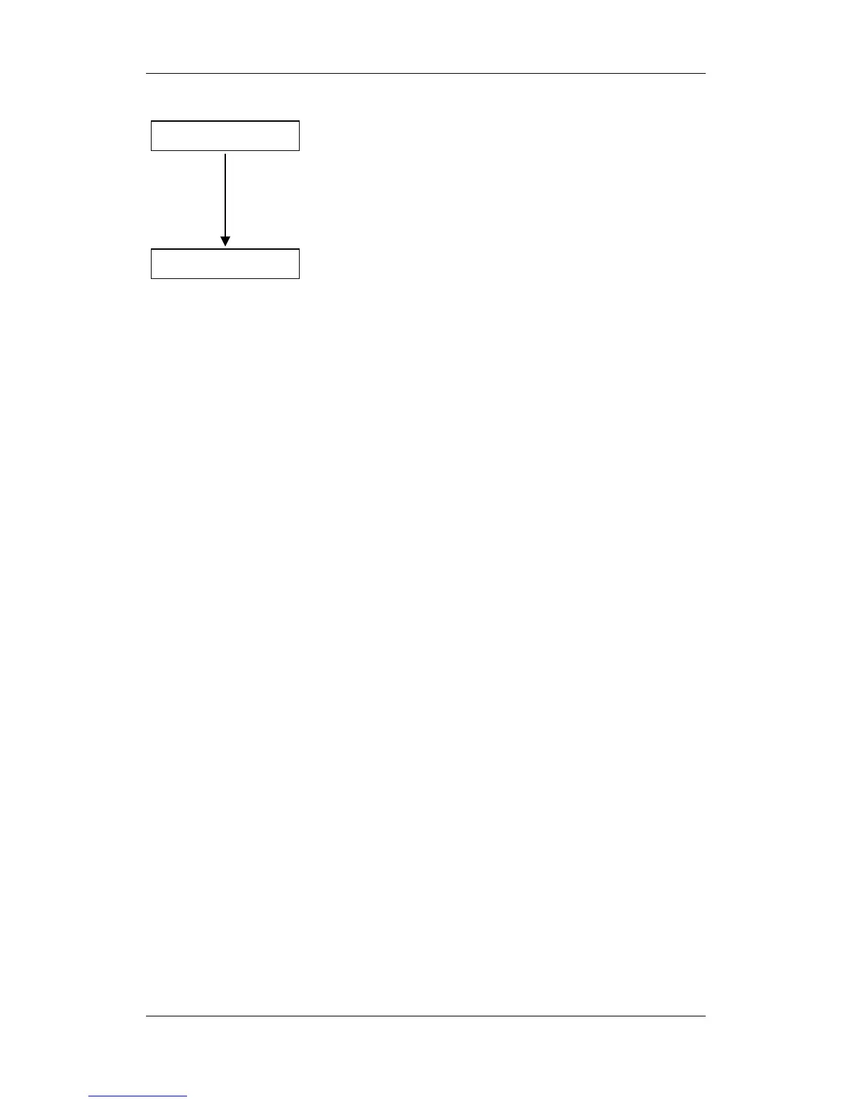
P370 = 1
P060 = 0
Start quick parameterization
0: No parameter change
1: Parameter change according to selected combination of
parameter modules
Note:
After the start, first of all an automatic factory setting is
carried out with P366 = 0, then the relevant parameterization
is performed.
Return to the user menu
Fig. 8-5 Sequence for parameterizing with parameter modules
Function diagram modules (function diagrams) are shown after the flow
chart for parameter modules stored in the unit software. On the first few
pages are the:
♦
setpoint and command sources, on the following pages are the
♦
analog outputs and the display parameters and the
♦
open-loop and closed-loop control types.
It is therefore possible to put together the function diagrams to exactly
suit the selected combination of setpoint/command source and
open/closed-loop control type. This will give you an overview of the
functionality parameterized in the units and of the necessary
assignment of the terminals.
The function parameters and visualization parameters specified in the
function diagrams are automatically adopted in the user menu and can
be visualized or changed there.
The parameter numbers of the user menu are entered in P360.
Function diagram
modules