12-pulse parallel connection
3.2 Configuration
12-pulse applications
18 Compact User Manual, 09/2015, A5E34871844H
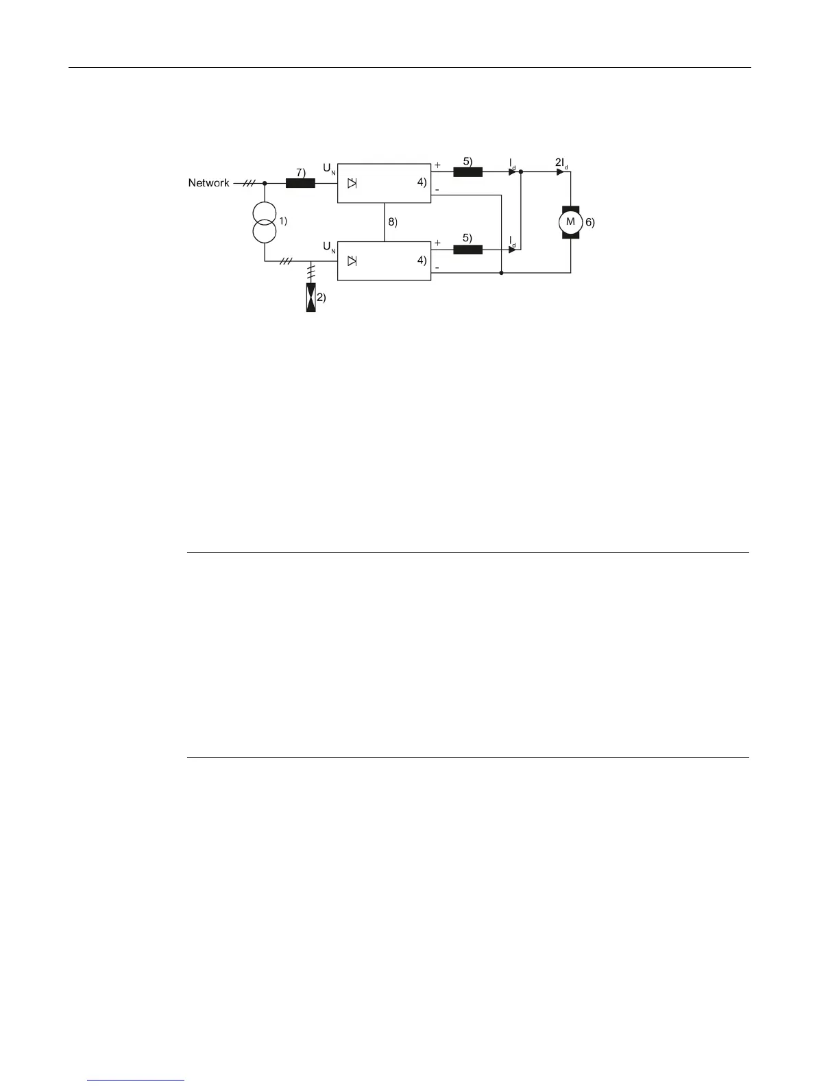
Application with isolation transformer
2) Overvoltage protection
8) Current setpoint input
U
N
= rated voltage of the line supply connected at the converter input
I
d
= direct current of a partial converter (½ total direct current)
Figure 3-7 Application with isolation transformer
Transformer: When there is a low-voltage rail, an isolation transformer with a voltage
transformation ratio of 1:1 is used upstream of a converter for a 30° phase offset.
Suitable vector groups for the transformer: Dy11, Yd11, Dy5, u
k
= 4 % to 6 %
Transformer type rating: S
T
= UN × 1,35 × 1,05 × Id
Note
If converters are connected in parallel in order to increase the current (parallel connection of
additional max. 5 devices per 6
-pulse branch is possible), a line reactor must be connected
upstream of each converter unit with min. 2% u
K
in order to decouple each converter. In
order to ensure symmetrical current distribution in the parallel converter units, the lowest
possible deviation of th
e impedance values of the individual line reactors is required. In
practice, a 3% difference can be achieved at a reasonable cost. The additional voltage drop
in the line reactors must be taken into account during the configuration.
which do not have any arm fuses and 4Q operation is possible at the
same time, every converter is to be supplied with a fuse on the DC side which has been
dimensioned according to its output current.

 Loading...


