12-pulse series connection
4.1 Topologies
12-pulse applications
Compact User Manual, 09/2015, A5E34871844H
29
Therefore, a conscious decision must be made:
● Low ripple, but no reduction of the reactive power:
→ operation with the same firing times (p51799 = 41)
● Low reactive power, but no reduction of the ripple:
→ Operation with sequence control (p51799 = 42)
The power unit of the slave converter must be connected to the 12-pulse transformer so that
its phases lag the phases of the line supply at the master by 30°. The phase sequence must
be the same.
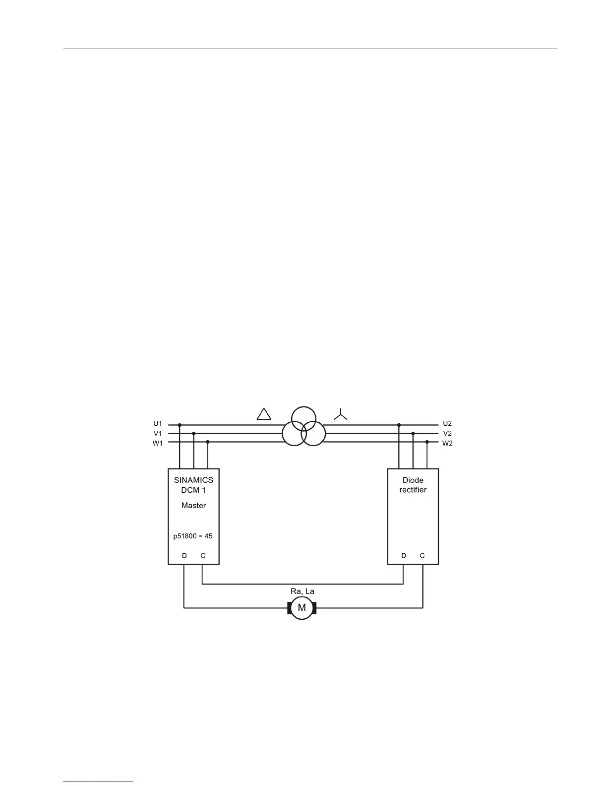
12-pulse series connection: controlled converter + uncontrolled converter
Topology
The following diagram shows the topology of a 12-pulse series connection of a SINAMICS
DCM 2-quadrant unit and a diode rectifier. (thyristor bridge B6 + diode rectifier)
Remark:
The incoming AC voltage of the controlled converter should be 10% to 15% higher than that
at the controlled converter, in order that the current can be reliably reduced down to 0.
Figure 4-3 12-pulse series connection: Controlled + uncontrolled rectifier, block diagram

 Loading...


