12-pulse series connection
4.2 Configuration
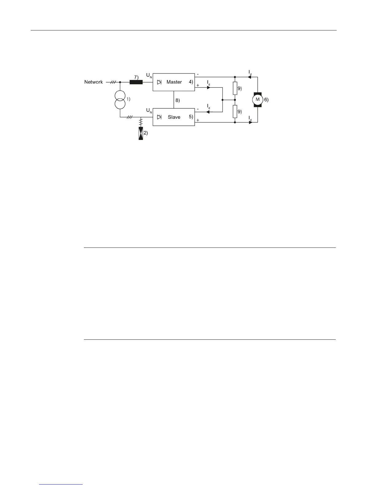
12-pulse applications
34 Compact User Manual, 09/2015, A5E34871844H
Application with isolation transformer
2) Overvoltage protection
U
N
= rated voltage of the line supply connected at the converter input
I
d
= direct current through both SINAMICS DCM devices and motor
Figure 4-6 Converter transformer dimensioning at low voltage
Transformer: When there is a low-voltage rail, an isolation transformer with a voltage
transformation ratio of 1:1 is used upstream of the slave converter for a 30° phase offset.
Suitable vector groups for the transformer: Dy11, Yd11, u
k
= 4 % to 6 %
Transformer type rating: S
T
= U
N
× 1,35 × 1,05 × I
d
Note
If converters are connected in parallel in order to increase the current (parallel connection of
additional max. 2 devices per 6
-pulse branch is possible), a line reactor must be connected
upstream of each converter unit with min. 2% u
K
in order to decouple each converter. In
order to ensure symmetrical current distribution in the parallel converter units, the lowest
possible deviati
on of the impedance values of the individual line reactors is required. In
practice, a 3% difference can be reached at a reasonable cost. The additional voltage drop
in the line reactors must be taken into account during the configuration.
e used which do not have any arm fuses and 4Q operation is possible at the
same time, every converter is to be supplied with a fuse on the DC side which has been
dimensioned according to its output current.
The output voltage of a 12-pulse series system is set by the insulation strength and the
semiconductor reverse voltages of the individual devices.
Devices with 690, 830 and 950 V
AC
have the same control module, i.e. the insulation against
ground is dimensioned for 950 V
AC
for all three devices. However, this voltage cannot be fully
utilized because series connection can cause a much higher voltage against ground in the
system in the event of a ground fault. In addition, the faulty functioning of the symmetry

 Loading...


