Marine-specific installation regulations
8.2 Integration of the components in the cabinet
Using SINAMICS G120 / G120C / S120 Blocksize converters in marine applications
28 Application Manual, 11/2019, A5E48346362A
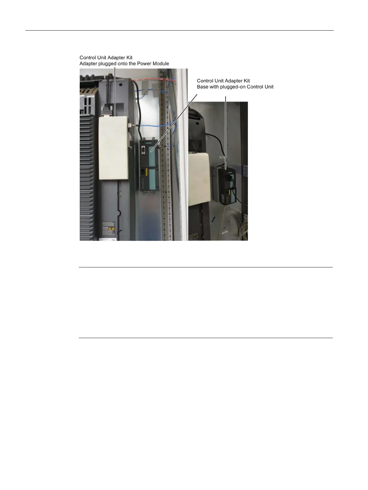
Figure 8-3 Control Unit Adapter Kit and separately installed Control Unit
Note
Integrating a Power Module into the control cabinet
•
The distance between the control cabinet base and the top of the chassis should not
exceed 1700 mm.
Power Modules, frame sizes FSD, FSE, FSF and FSG, should be arranged centered
(widthwise) in the control cabinet.
The drilling patterns for the mounting plate can be taken from the standard
documentation.

 Loading...


