Overview
PLC Subroutines Manual
8 Operating Instructions, 12/2012, 6FC5397-2EP10-0BA0
● PLC Programming Tool
– Symbol table: SYM1 to SYM32 (32 symbol tables)
– Subroutine: SBR0 to SBR63 (64 subroutines)
Structure of the symbol tables
The PLC subroutine library has been designed with symbol addressing method, which helps
you easily understand the PLC programs. All the addresses in the subroutine library use
symbols for programming. All the interface signals are named with symbols and assigned to
different symbol tables.
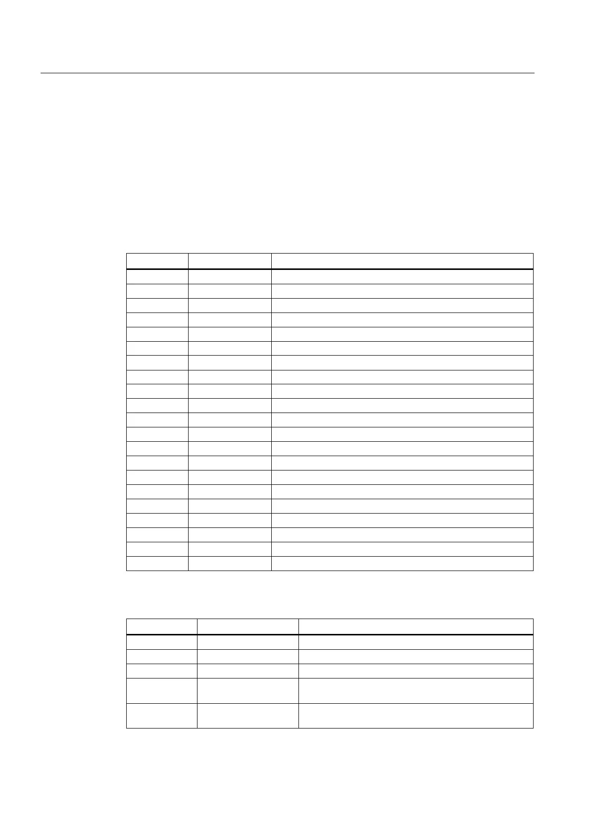
Symbol table Table name Descriptions
1 IO_1 Module I/O are defined by the manufacturer
2 IO_2 Distributed I/O are defined by the manufacturer
3, 5, 7, 13 Reserved for the manufacturer
6 MANMACH JOG function
14 ASUP ASUP function
15 PLC_sel_PP PLC selects part programs
16 IS_MCP Signals from/to the MCP
17 IS_HMI Signals from/to the HMI
18 IS_AUX Auxiliary functions from the NCK
19 IS_NCK Signals from/to the NCK
20 IS_CHA Signals from/to the channel
21 IS_AX1 Signals to/from axis 1
22 IS_AX2 Signals to/from axis 2
23 IS_AX3 Signals to/from axis 3
24 IS_AX4 Signals to/from axis 4
27 MD_PLC PLC machine data
28 ALARM User alarms
29 NV_MEM Non-volatile memory
30 SPC_MEM Special memory bit
31 SBR_MEM Global memory used in the sample applications and subroutines
32 RESVD1 Reserved for the sample applications and subroutines
Structure of the subroutines
Subroutine No. Name Description
0 to 19 - Reserved for the manufacturer
20 AUX_MCP Auxiliary function
21 AUX_LAMP Lamp control, called in the subroutine "AUX_MCP".
22 AUX_SAFE_DOOR
Safe door control, called in the subroutine "AUX_MCP" of
a milling application.
23 AUX_CHIP
Chip remover control, called in the subroutine
"AUX_MCP" of a milling application.