Connecting
3.3 Connecting the interfaces on the PPU
Electrical Installation Manual
30 Operating Instructions, 12/2014, 6FC5397-2EP10-0BA0
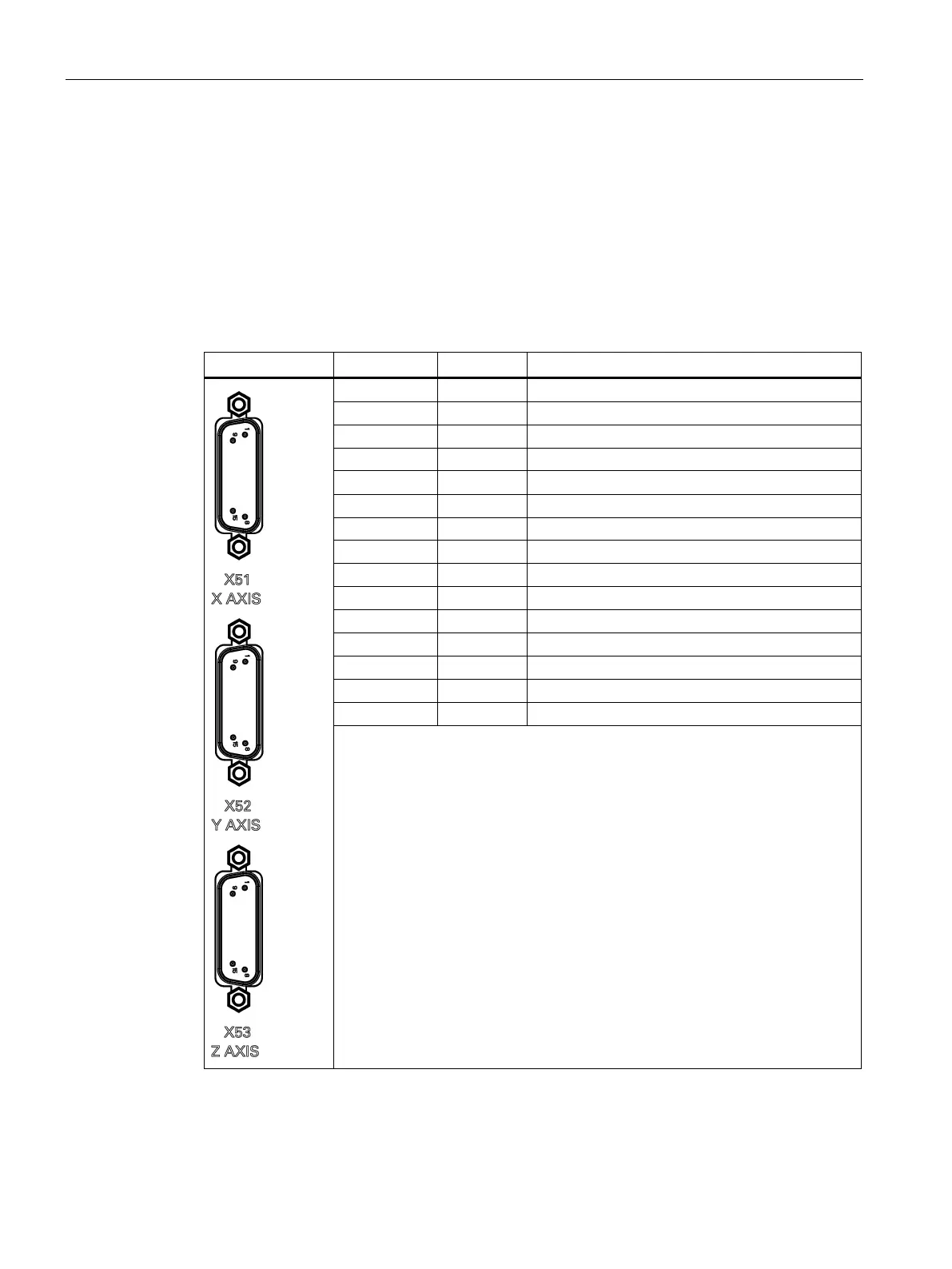
Pulse drive interfaces - X51, X52, X53
Pin assignment
Type Sub-D, 15-pin, male
Cable Type: drive cable
Max. length: 10m
1 PULSE+ PULSE, to drive side
2 DIR+ DIRECTION, to drive side
3 ENA+ ENABLE, to drive side
4 BERO Zero mark, from drive side
5 +24V POWER from the pin 1 of X200, +24V output
6 RST ALARM RESET, to drive side
7 M24 Ground
8 +24V POWER from the pin 1 of X200, +24V output
9 PULSE- NEGATIVE PULSE, to drive side
10 DIR- NEGATIVE DIRECTION, to drive side
11 ENA- NEGATIVE ENABLE, to drive side
12 +24V POWER from the pin 1 of X200, +24V output
13 M24 Ground
14 RDY DRIVE READY, from drive side
15 ALM ALARM, from drive side
The +24V and M24 signals at the pulse drive interfaces can only be used when
the +24V and M24 pins are connected at the interface X200.