Operating and Programming — Milling Page 50 808D
Create Part
Program
Part 2
s
Basic Theory
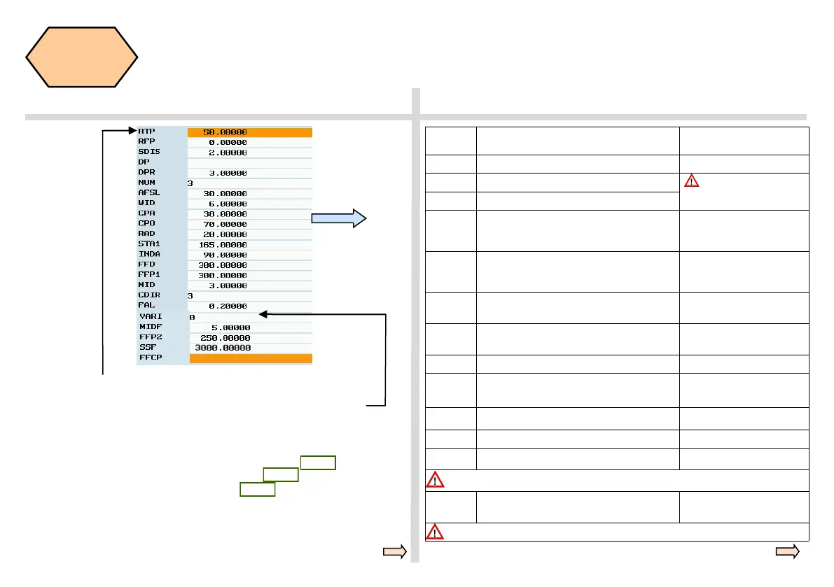
N210 SLOT2( 50.00000, 0.00000, 2.00000, , 3.00000, 3, 30.00000, 6.00000,
38.00000, 70.00000, 20.00000, 165.00000, 90.00000, 300.00000, 300.00000,
3.00000, 3, 0.20000, 2000, 5.00000, 250.00000, 3000.00000, )
Parame-
ters
Meanings Remarks
NUM=3 Three slots on the circle
AFSL=30 Angle slot length is 30º AFSL and WID jointly
decide the shape of the slot in
the plane
WID=6 Slot width is 6 mm
STA1=165
Start angle,angle between the effective work piece
horizontal coordinate in positive direction and the
first circle slot is 165º
INDA=90
Incremental angle, angle between the slots is 90º INDA=0, cycle will calculate
the incremental angle automati-
cally
MID=3 Maximal depth of one feed is 3 mm
MID=0 → complete the cutting
of the slot depth
CDIR=3
Milling direction G3 (in negative direction) Evaluate value 2→use G2 (in
positive direction)
FAL=0.2 Slot side, finishing allowance is 0.2 mm
VARI=0 The type of machining is complete machining
VARI=1→roughing
VARI=2→finishing
MIDF=5 Maximal feed depth of the finishing is 5 mm
FFP2=250 Feed rate of finishing is 250 mm/min
SSF=3000 Spindle speed for finishing is 3000 mm/min
If FFP2/SSF are not specified, then use the feed rate/spindle speed of rotation as default
FFCP= Feed rate at the center position on the circle
path ,unit is mm/min
Before recalling the cycle, you must set the tool radius compensation value.
For descriptions of RTP, RFP, SDIS, DP and DPR, please see page 40
For descriptions of CPA, CPO and RAD, please see page 45
For descriptions of FFD and FFP1, please see page 48
 Loading...


