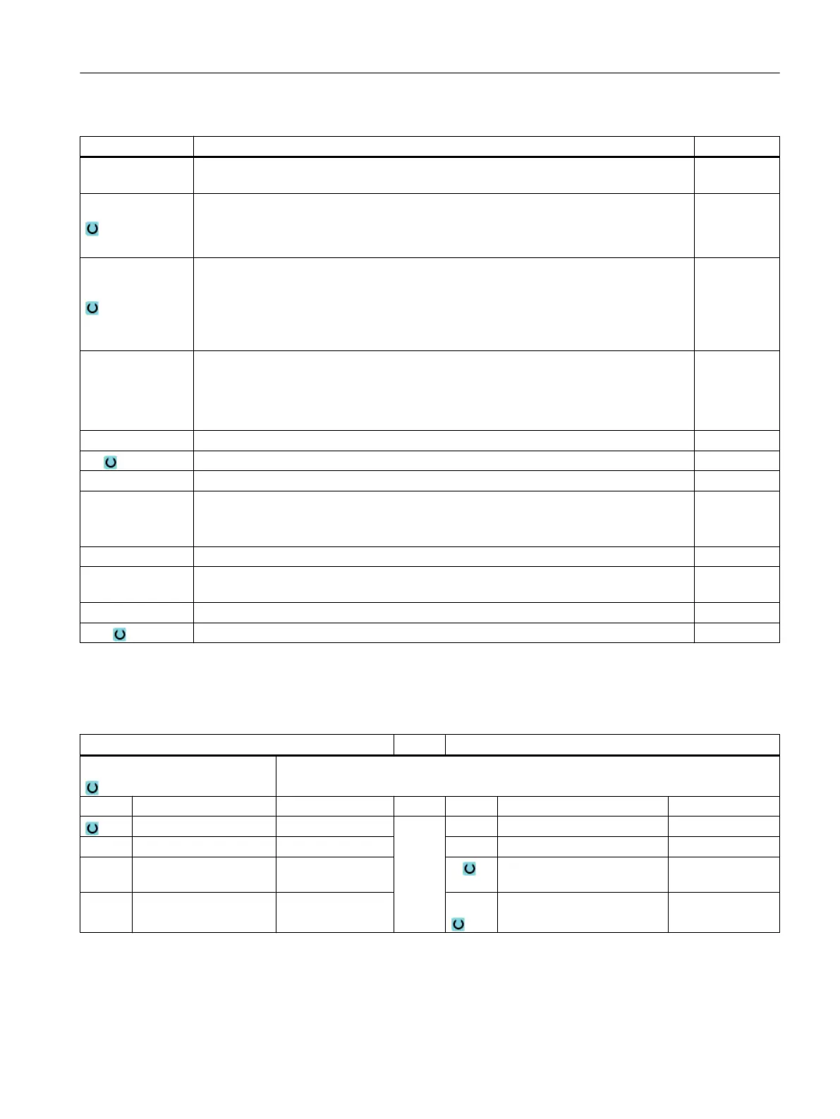
Parameter Description Unit
FZ
(only for G code)
Depth infeed rate *
Machining
● ∇ (roughing)
● ∇∇∇ (finishing)
● Chamfering
Machining posi‐
tion
● Single position
A circular spigot is machined at the programmed position (X0, Y0, Z0).
● Position pattern
Several circular spigots are machined in a position pattern
(e.g. full circle, pitch circle, grid, etc.).
X0
Y0
Z0
The positions refer to the reference point:
Reference point X – (for single position only)
Reference point Y – (for single position only)
Reference point Z – (single position only and G Code position pattern)
mm
mm
mm
∅ Diameter of spigot mm
Z1 Spigot depth (abs) or depth relative to Z0 (inc) - (only for ∇ and ∇∇∇) mm
DZ Maximum depth infeed - (only for ∇ and ∇∇∇) mm
UXY Plane finishing allowance for the length (L) and width (W) of the circular spigot.
Smaller circular spigot dimensions are obtained by calling the cycle again and program‐
ming it with a lower finishing allowance - (only for ∇ and ∇∇∇).
mm
UZ Depth finishing allowance (tool axis) - (only for ∇ and ∇∇∇) mm
∅1 Diameter of blank spigot (important for determining approach position) - (only for ∇ and
∇∇∇)
mm
FS Chamfer width for chamfering - (for chamfering only) mm
ZFS Insertion depth of tool tip (abs or inc) - (for chamfering only) mm
* Unit of feedrate as programmed before the cycle call
Parameters in the "Input simple" mode
G code program parameters ShopMill program parameters
Input
● simple
Milling direction T Tool name
RP Retraction plane mm D Cutting edge number
F Feedrate * F Feedrate mm/min
mm/rev
S / V Spindle speed or constant
cutting rate
rpm
m/min
Programming technological functions (cycles)
10.2 Milling
Milling
Operating Manual, 08/2018, 6FC5398-7CP41-0BA0 443
 Loading...


