Parameters in the "Input complete" mode
G code program parameters ShopMill program parameters
Input
● complete
PL Machining plane T Tool name
Milling direction D Cutting edge number
RP Retraction plane mm F Feedrate mm/min
mm/tooth
SC Safety clearance mm S / V Spindle speed or constant cutting
rate
rpm
m/min
F Feedrate *
Parameter Description Unit
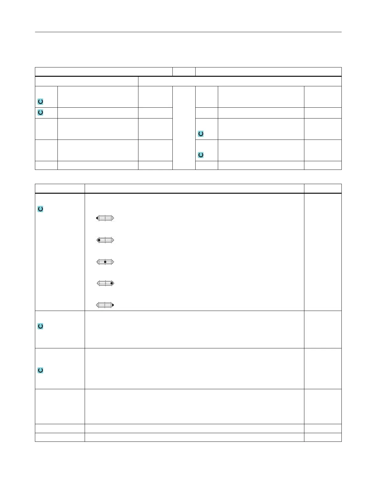
Reference point Position of the reference point:
● (lefthand edge)
● (inside left)
● (center)
● (inside right)
● (righthand edge)
Machining
● ∇ (roughing)
● ∇∇∇ (finishing)
● ∇∇∇ edge (edge finishing)
● Chamfering
Machining posi‐
tion
● Single position
A slot is milled at the programmed position (X0, Y0, Z0).
● Position pattern
Several slots are milled at the programmed position pattern (e.g. pitch circle, grid,
line).
X0
Y0
Z0
The positions refer to the reference point:
Reference point X – (only for single position)
Reference point Y – (only for single position)
Reference point Z – (only for single position and G code position pattern)
mm
mm
mm
W Slot width mm
L Slot length mm
Programming technological functions (cycles)
10.2 Milling
Milling
Operating Manual, 08/2018, 6FC5398-7CP41-0BA0 451
 Loading...


