Manual
1 Technical Description
1.5 Functional Description
1.5.8 Complex Functions (Arithmetic blocks c, d, h)
SIP ART DR24 6DR2410
C79000-G7476-C153-03
63
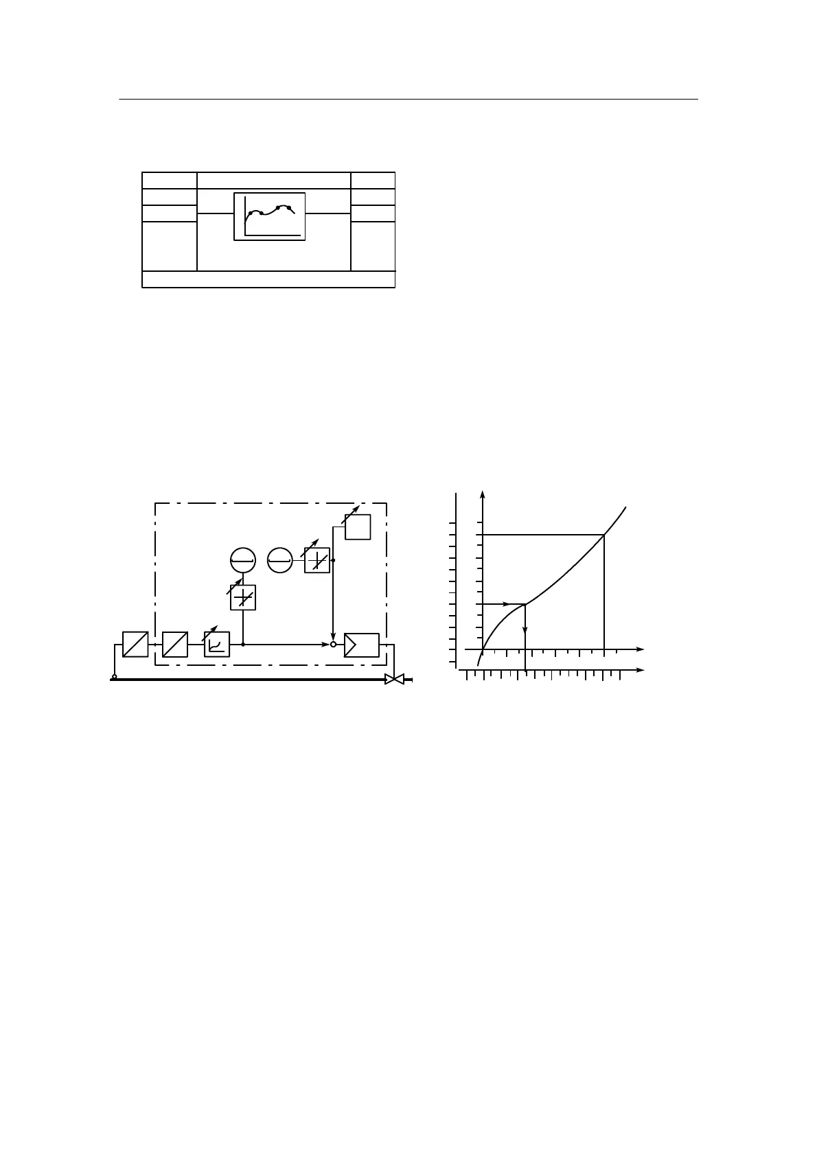
Function transmitter FUP1, FUP2 (parabola)
ncon
EA
Vertex --10, 00, 10 to 110
A
E
.A∩
c.F
--
∩ .1
n
---
FUP1, FUP2
(oFPA)
The function transmitter assigns every value of the input variable E in the range from --10 % to
+110 % an output variable A in the range from --199.9 % to +199.9 % by means of the function
entered by the user: A = F(E). The function is entered by the private parameters „vertex --10 ...
110” for --10 % to +110 % E in intervals of 10 %. Parabolae are set by the computing program
between these vertex values which interlink tangentially the vertex values so that a constant
function is produced. The vertex values at --10 % and +110 % E are required for the overflow .
The last rise remains constant in the case of further overmodulation of E. When using as a li-
nearizer for the indicators the linearization function is input by the 13 vertex values so that the
multiplication function gives a linear equation.
10006002000 1400 1600 1800
80
70
40
50
30
Figure 1--29 Using of function transmitter to
linearize non--linear process variables
for the display and control
--10 to 110
x
Phys.
W
i
dA
dE
00000000
w
+
x
xd
x1 (l)
x1
A
D
E
dA
dE
0
[%]
x
Phys
.
Vertex
values
110
x
1
[%]
˚C
Measuring range
200 to
1600 ˚C
10080604020
Figure 1--30 Sensor function e.g. from table
y
100
60
20
10
0
90
--10
40
100
60
20
80
--
˚C
Example: Linearization of the controlled variable x1
The vertex values 0 and 100 are set with 0 % and 100 % so that x
1
(l) is available again as the
normalized variable and the reference points for the definition of the display range of the x dis-
play are correct (see chapter 1.5.3, page 29).
To determine the vertex values, apply the sensor function according to figure 1--30 to 1--32
(page 64) and divide the measuring range into 0 to 100 % (x
Phys
in %). Then the vertex values
at--10%to+110%xonthex
Phys
axis are read in % and input one after the other in the config-
uring mode oFPA.
 Loading...


