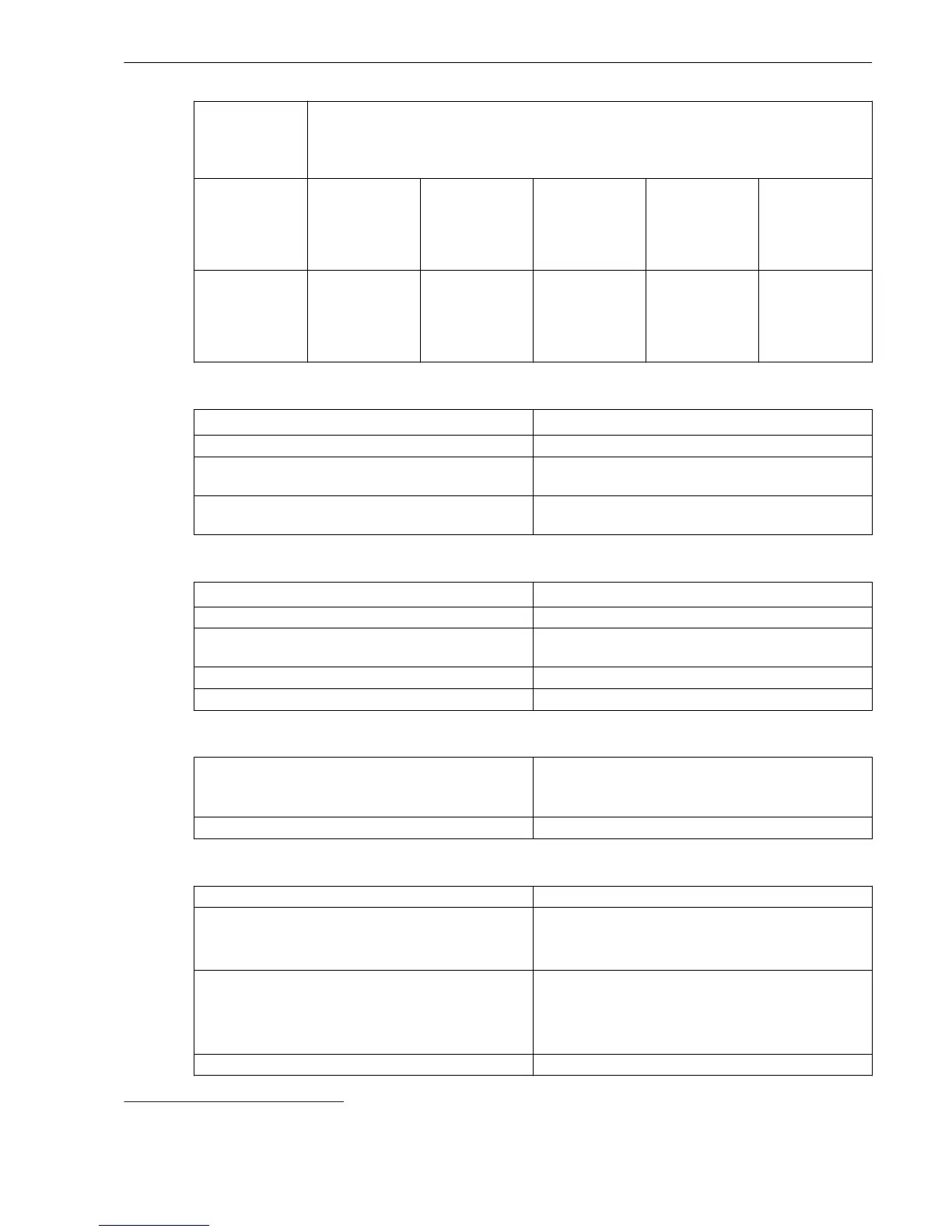
Type of
Construction
(Maximum
Dimensions)
Width over all x Height over all x Depth
12
(in Inches)
Surface-
mounted device
with integrated
on-site operation
panel
150 mm x
314 mm x
337 mm (5.91 x
12.36 x 13.27)
225 mm x
314 mm x
337 mm (8.86 x
12.36 x 13.27)
300 mm x
314 mm x
337 mm (11.81
x 12.36 x 13.27)
375 mm x
314 mm x
337 mm (14.76
x 12.36 x 13.27)
450 mm x
314 mm x
337 mm (17.72
x 12.36 x 13.27)
Surface-
mounted device
with detached
on-site operation
panel
150 mm x
314 mm x
230 mm (5.91 x
12.36 x 9.06)
225 mm x
314 mm x
230 mm (8.86 x
12.36 x 9.06)
300 mm x
314 mm x
230 mm (11.81
x 12.36 x 9.06)
375 mm x
314 mm x
230 mm (14.76
x 12.36 x 9.06)
450 mm x
314 mm x
230 mm (17.72
x 12.36 x 9.06)
Expansion Module Dimensions
Type of Construction (Maximum Dimensions)
Width x Height x Depth
13
(in Inches)
Flush-mounting device 75 mm x 268 mm x 229 mm (2.95 x 10.55 x 9.02)
Surface-mounted device with integrated on-site oper-
ation panel
75 mm x 314 mm x 337 mm (2.95 x 12.36 x 13.27)
Surface-mounted device with detached on-site opera-
tion panel
75 mm x 314 mm x 230 mm (2.95 x 12.36 x 9.06)
Plug-In Module Dimensions
Type of Construction (Maximum Dimensions)
Width x Height x Depth (in Inches)
USART-Ax-xEL, ETH-Bx-xEL 61 mm x 45 mm x 120.5 mm (2.4 x 1.77 x 4.74)
USART-Ax-xFO, ETH-Bx-xFO (without protection
cover)
61 mm x 45 mm x 132.5 mm (2.4 x 1.77 x 5.22)
ANAI-CA-4EL 61 mm x 45 mm x 119.5 mm (2.4 x 1.77 x 4.7)
ARC-CD-3FO 61 mm x 45 mm x 120.5 mm (2.4 x 1.77 x 4.74)
Minimum Bending Radii of the Connecting Cables Between the On-Site Operation Panel and the Base Module
Fiber-optic cable
R = 50 mm
Pay attention to the length of the cable protection
sleeve, which you must also include in calculations.
D-Sub cable R = 50 mm (minimum bending radius)
Degree of Protection to IEC 60529
For equipment in the surface-mounting housing
IP50
For equipment in the flush-mounting housing Front IP51
Back side of the modular devices IP50
Back side of the non-modular devices IP40
For operator protection IP2x for current terminal (installed removed)
IP1x for voltage terminal (removed/without cover)
IP2x for voltage terminal (removed/with cover)
IP2x for voltage terminal (installed)
Degree of pollution, IEC 60255-27 2
12
Width and depth rounded to whole numbers in mm
13
Width and depth rounded to whole numbers in mm
Technical Data
11.1 General Device Data
SIPROTEC 5, Low-Impedance Busbar Protection 7SS85, Manual 561
C53000-G5040-C019-6, Edition 06.2016

 Loading...